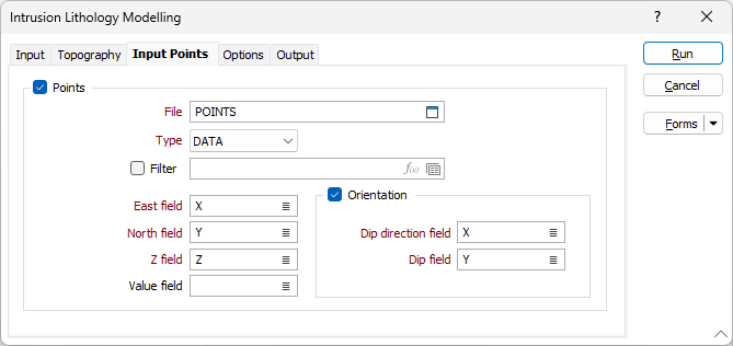
Input Points
Use the Inputs Points tab to specify a set of points
The points in the file represent contact points that the implicit model will try to go through.
The Structural Ribbons defined represent planar and linear oriented structures that influence and shape the implicit model.
Points
Select this check box to constrain the modelling process so that surface of the model is coincident with a set of input points.
File
Double click (or click on the Select icon) to select an Input file. Typically, the Type of the Input file will be a DAT file containing point sample data. Other file types are also supported; including Survey, Structure and Report.
You can also click the Pick from Vizex button to collapse the form and interactively select a layer containing the file to be inserted and return to the form.
You can optionally apply a Filter to the records in the file.
Note: For the attributes on the tab, you can select an value using the list button or right-click and select Edit Expression to open the Expression Editor and use an expression. Note also the information in Output Field Name Attributes.
East, North and Z fields
Specify the names of the fields in which Easting, Northing, and Z coordinates are stored in the Input points file.
Orientation
The orientation of the generated wireframe is influenced by the Dip and Dip Direction of the points or strings in the Input file.
Use the inputs to include structural information (dip and dip direction) to points, and the surface will honour that orientation. Enter an orientation that is normal to the surface where it coincides with the input points.
Double-click (or click on the List icon) to select the name of the Dip Direction field (see Dip and Dip Direction). The available fall direction range is 0-360 degrees.
Double-click (or click on the List icon) to select the name of the Dip field (see Dip and Dip Direction). The available incidence angle range is 90-(-90) degrees.
Any dip direction or dip values outside of the specified ranges (i.e. negative dips) are ignored and a warning message is displayed after processing is complete.
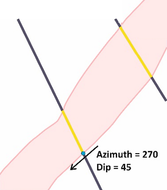
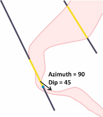
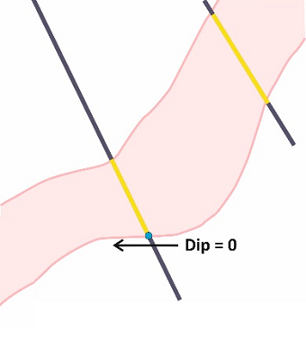
Examples of use, cross-sectional view:
|
Dip direction = 270, Dip =90 |
Dip direction = 270, Dip = 45 |
|
|
|
|
Dip Direction = 90, Dip = 45 |
Dip direction = 270, Dip =0 |
|
|
|

Value field
Optionally, select a field in the Input file which contains indicator values to influence your model. The values in this field will typically be:
-
1 (Inside)
-
-1 (Outside)
-
0 (Boundary
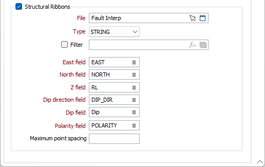
Structural Ribbons
Select this check box to constrain the modelling process so that the surface of the model is coincident with specified structural ribbons.
File
Double click in the File field or use the folder icon to select the file to be used with the model. You can also click the Pick from Vizex button to collapse the form and interactively select a layer containing the file to be inserted and return to the form.
Filter
Optionally, you can use a filter to determine the values of the structural ribbons that will affect the model.
Easting, Northing, Z
Specify the names of the fields to which East, North and Z coordinates will be written.
Dip direction, Dip
Specify the fields containing values which represent the bearing of the formation Dip direction and the Dip angle of formation, respectively.
Polarity field
Specify the field containing the Polarity value for the structural ribbon. The values in this field will typically be:
-
1 (Positive)
-
-1 (Negative)
Maximum point spacing
Specify a maximum separation between points value in order to insert points where necessary to make the segmentation of the structural ribbons more uniform. As a result, a wireframe generated from the string will be smoother.