Evaluate Pit Shell
![]()
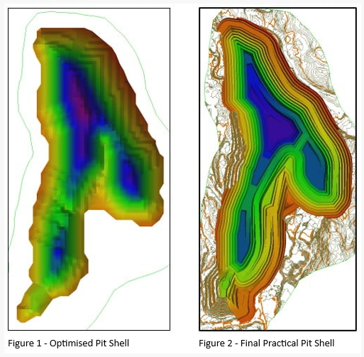
The Evaluate Pit Shell tool is used to compare different designs for the same deposit. This allows the engineer to select different scenarios for the design, based on variations of road position, slope angle, bench configuration, and other details. This allows comparison between an optimum pit shell and an operational shell to be enable quantifying of the dilution for the operational shell. As the optimised shell does not use roads, a difference is expected between optimum vs designed (operational) shells, and this difference can be quantified in order to validate the design.
For example, in the below comparison, the pit shell shape is similar but differences will be apparent in tonnage, volume, metal content and eventually Value.
Pit Surfaces
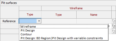
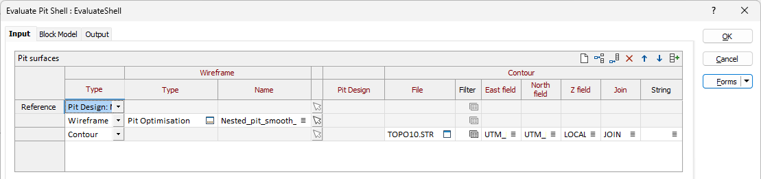
In the Evaluate Pit Shell form, on the Input tab, use the Pit Surfaces grid to define the Reference Pit Shell and the shells with which it is to be compared. The reference shell should be an optimum pit shell; a pit coming from a mathematical optimisation of the deposit - usually from a pit optimiser tool or similar process. The comparison shells can be any of the following:
-
Pit Design file
-
Solid Wireframe
-
Shell, DTM (Open Wireframe)
-
String Files exported from another Pit Design
-
Contours
Where multiple targets are defined, the reference for each target is the preceding entry - supporting processing for a list of end-of-period surfaces.
Type
Use the drop down list in the first row to select the Type for the Reference pit shell.
For the Reference shell,
-
Pit Design - Select the active Pit Design from the Type field or select the Pit Design File from the field provided.
To add the comparison input files to the evaluation, you can add rows to the grid. Use the buttons on the local toolbar to Manage the rows in the list. Select from the following Types.
-
Pit Design - Select the Pit Design File from the field provided. This will be automatically filled if you selected the active Pit Design.
-
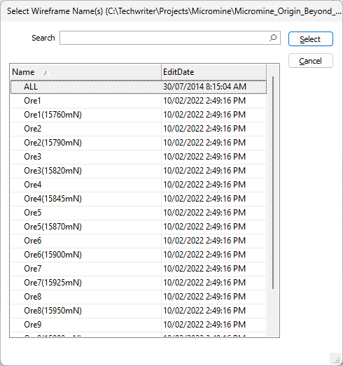
Wireframe - Select the wireframe Type and Name from the fields provided. You can also use the Pick from Vizex button (or select the context menu option where available) to collapse the form and interactively select the required Wireframe to insert and return to the form.
-
Contour - Select the contour String File from the field provided.
-
Specify the East, North and Z fields along with the Join and String fields for the contour, or accept the defaults.
-
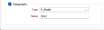
Topography
Specifying Topography for the Evaluation will combine the topography with the specified surfaces so that proper cut/fill solids can be generated.
Select the Topography option and select a wireframe Type for the topography. The Select Wireframe Name form will open and you can select a Name for the topography wireframe type.
You can also use the Pick from Vizex button (or select the context menu option where available) to collapse the form and interactively select the required Wireframe to insert and return to the form.
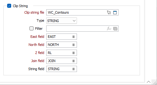
Clip String
Select the Clip String option to specify and define a string file with clipping polygons. If you specify a string, the reference and target will be clipped orthogonal to the plane of best fit for the polygons prior to processing.
Clip string file
Select a file type and double-click (F3) to select the file containing the strings to be clipped. You can also click the Pick from Vizex button to collapse the form and interactively select a layer containing the file to be inserted and return to the form.
If required, select a filter or create one using the Expression Editor.
Easting and Northing and Z fields
Specify the names of the fields in which Easting, Northing, and (optionally) Z coordinates are stored in the input file.
Join field
Specify the name of the field containing values which define whether data points will be joined by a line i.e. strung. If successive records have the same value in this field and no String field is defined a line will join the points. If a String field is defined, then values in each field in successive records must be the same before the points will be strung.
String field
In most forms, the String field is an optional generic attribute used to store a secondary input such as a code. Traditionally, this field has also been used with the Join field to define whether data points should be joined by a line, or strung, hence the name.
You can continue configuration of the Pit Shell Evaluation tool on the Block Model tab.
Forms
Click the Forms button to select and open a saved form set, or if a form set has been loaded, save the current form set.
By design, the Forms button is not available for loaded Vizex layers (i.e. when opening the form set properties of a layer in the Vizex Layer Display pane). In Vizex, the Forms button is only available for new forms opened via the Home tab or the Vizex tab, in the Layer group (or by double-clicking on a form type node in the Vizex Layer Types pane).
Save and Save As
Click the Save button to save the changes you have made to the form set. Click Save As to save your changes as a new form set. Save As will default to the first available form set number.
Reset
Click Reset to clear the form of all values and reset the form to its default state.
Reset Tab
For tabbed forms, select Reset Tab to clear the active tab of all values and reset the tab to its default state - without making any changes to other tabs in the dialog.
Undo and Redo
Click Undo (CTRL + Z) to undo recent changes in the form. After an Undo, click Redo (CTRL + Y) to restore the last change that was undone.
Collapse
Collapse (roll-up) the form to preview a chart, or preview the results of an operation in Vizex, or obtain input values from Vizex, the Property Window, the File Editor, or the Plot Editor.