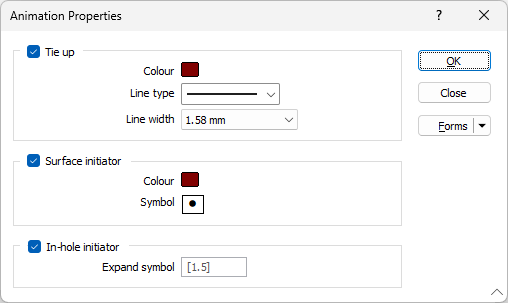
Options
![]()
Colours initially default to the colour selected on the Firing Sequence tab of the Blast Design. The colours you select here will not change the colour setting on that tab of the form.
Tie up
Select this check box to display the final tie-in of the blast, using a nominated colour, line type and line width.
Colour
Double click (F3) to select the colour that will be used to draw the tie-in lines.
Line type
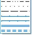
Select a line type. A preview of each line type is shown in the drop-down list. A variety of solid, dotted, and dashed line styles are available for selection.
Note: Extended line styles such as double lines are not compatible with 2D plots (they will render as a solid line) and will only display properly in Vizex and 3D Vizex plots (and screenshots). Extended line styles are displayed in blue in the Line Type drop down.
Line width
Select a (THIN, MEDIUM, THICK, or custom) line width from the drop-down list. An extensive selection of custom widths (in millimetres) are available for selection.
Surface Initiator
Select this check box to display the initiators at the blasthole collars.
Colour
Select the colour that will be used for the initiators at the blasthole collars.
Symbol
Double-click the Symbol box to choose a symbol for the surface initiators. You can source symbols from a wide range of True Type Fonts.
In-hole Initiator
Select this check box to animate the in-hole initiators. This is achieved by expanding the symbol used to denote the surface initiators.
Expand symbol
Accept the default or enter an Expand symbol value.