Viewing Points
Micromine Point files (.DAT) can be visualised in the Viewer. Point files created in Micromine Origin & Beyond can be uploaded to the linked Nexus project using the Upload Files option in the right-click menu.
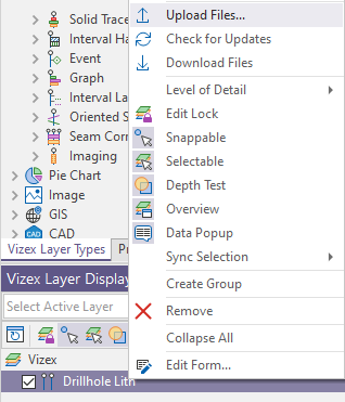
The files will appear in the Libraries and Projects selected for the upload, and will be shown with an eye icon that will open the file in the Viewer.
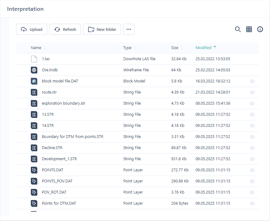
Viewable objects can be opened from the Project or Library directly, from the Click to preview link in the Info panel, or from the Select Object form from the Layers Panel.
To view a Points object,
-
Select Viewer from the Navigation menu.
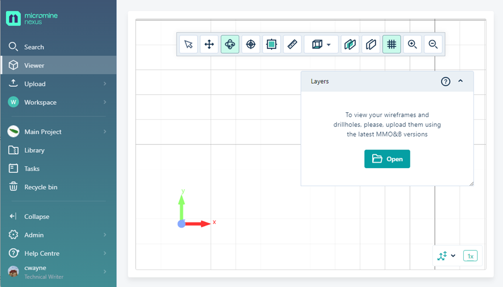
The Open button in the Layers panel is used to select the object to be displayed in the Viewer.
-
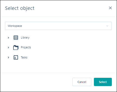
Click Open to display the Select Object form.
-
Use the drop down to select the relevant Workspace and navigate to the object to be visualised using the Library, Projects and Tasks lists.
Note: Any object that cannot be viewed will not appear in these lists.
-
Click OK.
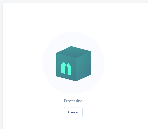
The Viewer will display an animation while rendering of the object is in progress.
When you open a valid Points file, it will be displayed in the Viewer grid. It can be examined and manipulated using the tools provided in the toolbar. See Viewer Tools.
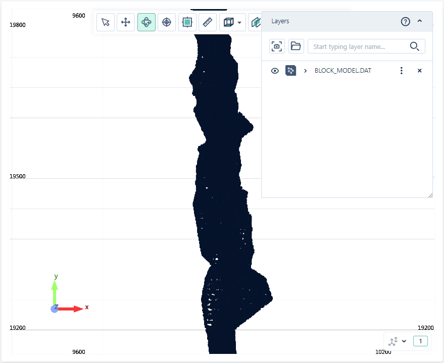
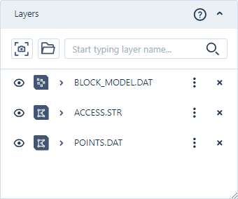
Any files you have opened are displayed in the Layers panel.
If you expand a point file entry in the panel, the Colour layer including version information is displayed:
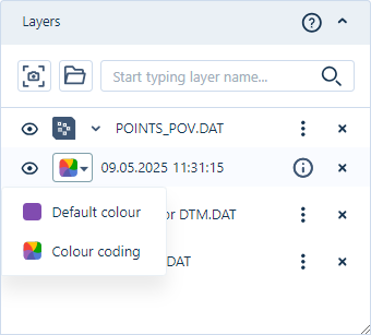
As shown above, you can select the Default colour for the point file display, or configure Colour coding for the points.
The Basic colours, Advanced and Custom tabs for the Default colour option provide increasingly expansive colour palettes to use for selecting your default colour.
If you select the Colour coding option, the Colour coding panel will open and you can select the Colour field and configure the colours for display - see Colour Coding.
With the tools in the Layers Panel you can save and share a scene from the Viewer, open additional files, search for a file in the panel and more. See Layers Panel for more details on the available tools.
The More menu for each object in the panel provides access to a number of tools and options which can be used to select the file version, open the Object Page and File Information, Download and Navigate links, configure field mappings and string thickness and more. See More Menu for information on the available tools.

Fields Mapping
For Point files, if you select the Fields mapping option, a dialog is displayed from which you can map Easting, Northing, Z and Join fields.
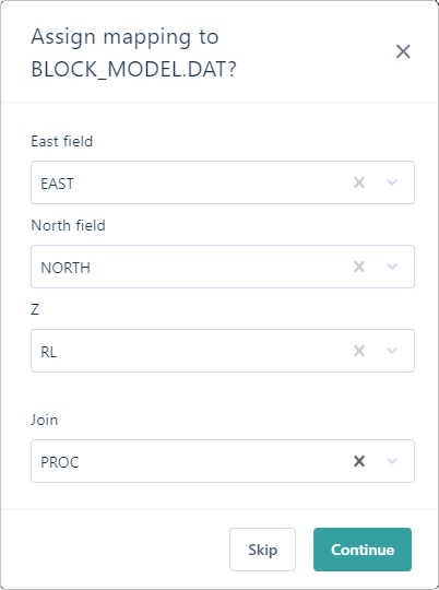
-
Select the required fields from each drop down and
-
Click Continue to apply the mapping.
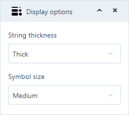
Display Options
To configure the String thickness and Symbol size settings for the points file display,
-
Select Display options from the More menu.
The Display options dialog is opened:
-
Use the String thickness drop down to select Thin, Medium or Thick string thickness display.
-
Set the Symbol size drop down to the required symbol display size - Small, Medium or Large.
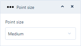
Note: For points files that do not contain any strings, the Point size option is available to select the size of the point display:
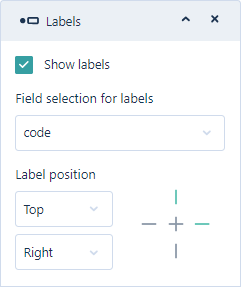
Labels
To display labels for an attribute in your point file,
-
Click the Labels option on the More menu.
The Labels dialog opens:
-
Select the Show labels option to enable the display of labels for the file in the Viewer.
-
From the drop down list of the attributes in the file, select the Field to be used for the labels.
Using the Label position options you can select the placement of the labels in the display.
-
In the first drop down, select whether the label will sit at the Top, Centre or Bottom of the labelled point.
-
In the second drop down, select whether the label will sit at the Left, Centre or Right of the point it is labelling.
The Cross at the right of the Label position options provides a preview of the location for the label that you have set.
For example, in the above dialog Top and Right are selected and so the top and right part of the cross are coloured green. If Centre and Left were selected, the preview would appear as follows:

If you select a point in the display using the Select tool, the coordinates of that point are displayed in a pop up dialog:

A number of tools are available from the Toolbar. Using the Viewer Tools you can perform various actions with the object, including moving it, rotating it, defining a section and more.