Design Regions
Select the Use Multiple Stope Design Regions check box to set the parameters of up to 10 stope design regions). You can then choose how the boundaries of the stope design regions are defined.
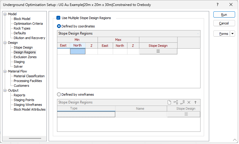
Defined by coordinates
Select this option to delineate regions for which different stope design parameters apply by specifying ranges of coordinate values.
Min East
(Min/Max coordinates only.) Specify the easting coordinate for the lower extremity of the region.
Min North
(Min/Max coordinates only.) Specify the northing coordinate for the lower extremity of the region.
Min Z
(Min/Max coordinates only.) Specify the elevation (Z) coordinate for the lower extremity of the region.
Max East
(Min/Max coordinates only.) Specify the easting coordinate for the upper extremity of the region.
Max North
(Min/Max coordinates only.) Specify the northing coordinate for the upper extremity of the region.
Max Z
(Min/Max coordinates only.) Specify the elevation (Z) coordinate for the upper extremity of the region.
Stope Design
Select the form set that specifies the axes and the alignment of the stopes and optionally edit those parameters interactively. See: Default Stope Design & Stope Alignment
Use the buttons on the local toolbar to Manage the rows in the list.
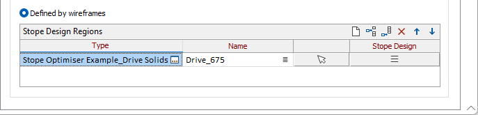
Defined by wireframes
Wireframe Type/Name
Select a wireframe of a specified Type and Name to define each stope region. Use the buttons in the toolbar to Manage the rows in the list. For each wireframe you add to the grid, you can specify a Name. You can also use the Pick from Vizex button (or select the context menu option where available) to collapse the form and interactively select the required Wireframe to insert and return to the form.
Stope Design
Select the form set that specifies the axes and the alignment of the stopes and optionally edit those parameters interactively. See: Default Stope Design & Stope Alignment