Coordinate Grid Settings
![]()
This form has three tabs, each with settings that control:
- which grids are active and the space in which they operate
- the appearance (labelling, line styles, transparency etc.) of the grid
- the display of an orientation axis tool
The Configuration tab of the Coordinate Grid Settings form defines the space that the coordinate grids work in. Here you can fine-tune the spacing and the extents of the grids you have made active.
Grid type
Choose the type of coordinate grid to display.
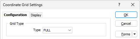
- FULL draws lines from one side of the paper to the other.
- CROSSES draws ticks around the plot border and crosses wherever grid lines intersect.
- TICKS draws ticks around the plot border.
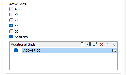
Active Grids
Use the options provided here to enable Auto Working Plane, or explicitly set the working plane, and select which grids are active.
Enable Auto Working Plane
The Auto working plane option will choose the best fit out of the other grids and apply that grid, depending on the current view:
-
If clipping is not enabled then the current view direction is compared with the X, Y and Z axis. If it is within an angle tolerance of the axis, then the corresponding grid is chosen, otherwise the 3D grid is chosen.
-
If clipping is enabled, the Auto working plane option will always choose the section grid.
If you are currently in an orthogonal view, then this will be taken as the current plane setting and the Auto Working Plane will remain in that orientation until you switch to a different orthogonal view.
For example:
If you are currently in Plan view, the Auto Working plane will be equivalent to the XY Working plane and will stay in that plane until a different orthogonal view is selected. So if you switch to Looking North, the Auto Working Plane will be equivalent to the YZ Working Plane.
See ‘Turn off Auto Working Plane in 3D views’ below.
Enable 3D Grid
If you are working in 3D mode, select this option to enable a 3D grid. See Turn off 3D Grid in orthogonal views.
The Display Margin setting in System Options is used to set the width of the grid margin. To change the margin width:
-
Click the Project tab to open the backstage menu.
-
Select the User Interface tab of the Options | System | System Options form.
Enable Additional Grids
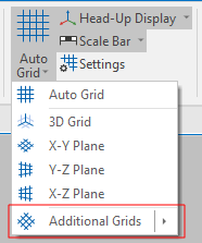
Select the Enable Additional Grids option to enable or disable additional grids as a group. The state of this check box can also be toggled on or off on the Vizex tab, in the Grid group, by selecting Auto Grid | Additional Grids:
You can also assign a shortcut key to the Enable Additional Grids command:
-
Click the Project tab to open the backstage menu.
-
On the backstage menu, in the Options | Keyboard Shortcuts group, select Customise > Keyboard Shortcuts.
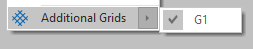
To individually show or hide additional grids use the check boxes in the Additional Grids list:
For more information, see: Other Grids
Active Grid Options
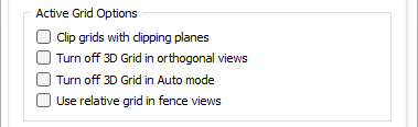
Clip grids with clipping planes
If clipping is enabled, the Auto working plane option will always choose the section grid.
If you are viewing your data in section and have a grid enabled, but Auto Working Plane is not enabled, select this option to clip the grid to the section extents.
You may want to enable a grid in the XY Working Plane, for example, to see where the clipped section sits in X-Y space.
Turn off 3D Grid in orthogonal views
If a 3D grid is enabled, but you prefer to see the 3D grid in a 3D view only, select this option to automatically turn off the 3D grid while you are in orthogonal mode.
Turn off 3D Grid in Auto mode
If you select the Turn off 3D Grid in Auto mode option, the Auto Grid disappears when you move out of one of the orthogonal views - i.e. the 3D Grid is not shown.
Note: If the permanent 3D Grid is displayed, it will not be affected by this option, unless the Auto Grid option is also enabled, in which case both will be turned off when you move out of an orthogonal view.
Use relative grid in fence views
Select this check box to enable the relative grid in fence views (polyline sections). If this option is not selected, the application will draw the regular grid for each segment, as it would for a normal transform section.
User-defined Line Spacing and Grid Extents
If these check box options are selected, the active grids will take their spacing and extent information from the settings you define.
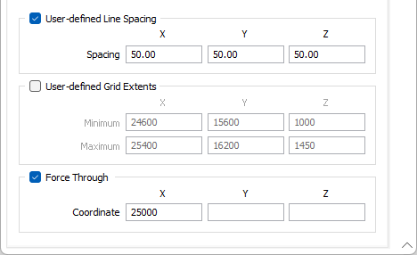
If the line spacing or the extents you enter are invalid, then the line spacing or extents of the active grids will be calculated automatically.
Entering user-defined values may be necessary when the line spacing and grid extents calculated automatically are not suitable for your data. Auto spacing might be too coarse, for example, and you may prefer a finer spacing.
If the spacing or extents you enter are invalid, then the spacing or extents of the grid will be calculated automatically.
If setting are incomplete the function will always attempt to use any valid settings you have entered.
Force Through
Sometimes it is necessary to force the grid lines through a particular coordinate.
For example, a grid with a 20m spacing will, by default, be running through 100m, 120m and 140m. You may require the grid to pass through 90m, 110m and 130m. In this case, enter one of these values and the grid lines will be adjusted automatically.
If force through values are not defined, the default is 0, or the user-defined minimum values (if user-defined extents have been specified).
Forms
Click the Forms button to select and open a saved form set, or if a form set has been loaded, save the current form set.
Save As
Click on the Save As button to save the settings you have made as a form set.
Apply
Click the Apply button to apply the settings you have made without closing the Grid Settings form. You can then check the effect your settings and adjust them if needed.