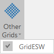
Other Grids
![]()
To enable or disable grids individually use the menu:
A typical use for an additional grid is to overlay a local project grid onto UTM coordinates, with the local grid oriented to local north and limited to the project extent. Each additional grid has independent options for setting the area of coverage, the appearance of lines and labels, and optionally defining a plane grid coordinate transformation.
To add a new coordinate grid:
- Open the Coordinate Grid Settings form.
- On the Configuration tab, select the Enable additional grids check box (see below).
- Right-click a row in the Additional Grids list and choose New from the pop-up menu. (If necessary, use the Append Row button on the Additional Grids toolbar to add another row.)
- The Additional Grids grid list has two columns, a check box to enable/disable the grid and an embedded form set defining the properties of the grid.

Enable Additional Grids
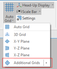
Select the Enable Additional Grids option to enable or disable additional grids as a group. The state of this check box can also be toggled on or off on the Vizex tab, in the Grid group, by selecting Auto Grid | Additional Grids:
You can also assign a shortcut key to the Enable Additional Grids command:
-
Click the Project tab to open the backstage menu.
-
On the backstage menu, in the Options | Keyboard Shortcuts group, select Customise > Keyboard Shortcuts.
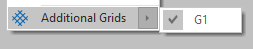
To individually show or hide additional grids use the check boxes in the Additional Grids list:
When the Enable Additional Grids option is selected, any change to the working plane will be applied to the primary grid and all additional grids.
When this option is not selected, any change to the working plane will be applied to the primary grid only. The working plane of additional grids must be toggled explicitly for each grid.
This makes it possible to toggle the working plane of additional grids without affecting the working plane, or the visibility, of the primary grid.
Variable grid spacing using expressions
Dynamic field expressions are supported:
When an expression is defined for the spacing, minimum values are compulsory and force through is disabled since a starting point to begin the variable spacing is required.
The first grid line will be drawn with value = minimum and index = 0. The spacing expression is then evaluated for that value and index. The spacing returned is then added to the value and the index is incremented until either the value is greater than the maximum or the spacing is less than or equal to 0.
The following is an example of a correctly formatted line spacing expression:
if [Index] <= 10 then
  6.0
elsif [Index] <= 12 then
  8.0
elsif [Index] <= 20 then
  10.0
else
  8.0
endif
Only positive index values are allowed.