Transformation
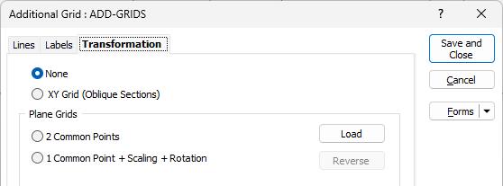
Use the Transformation tab of the Additional Grid form to allow the grid to have a coordinate system which is different to that of the underlying layer in Vizex.
None
Do not apply a grid transformation.

XY Grid (Oblique Sections)
Select this option to display an X axis grid showing the distance along the section line, with 0 in the centre of the frame and with the Y axis grid being the real Z axis. All other options on the Transformation tab of the form are disabled.
Plane Grids
When you apply a Plane Grid transformation, you can choose from the following options:
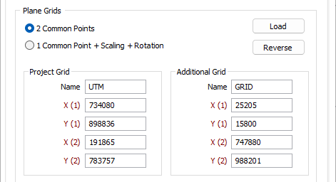
2 Common Points
Select this option to define the relationship between the grid and the underlying layer by entering X and Y coordinates for two corresponding points in both grid systems.

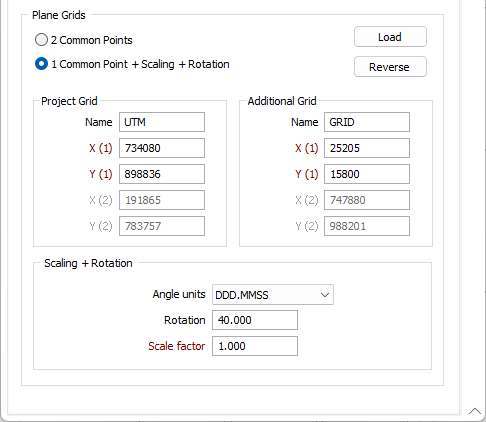
1 common Point + Scaling + Rotation
Select this option if you know the coordinates of one point in both grid systems. You must also specify the angle between the North directions of the grids, and any difference in scale between the grids.

1 Common Point
Enter the Easting and Northing coordinates of a known point in both grid systems.
Angle Units
Specify the angle units that will be used to measure the angle between the North directions of the grids.
Rotation
Specify the angle between the North directions of the grids by entering a rotation value.
Scale factor
Enter a factor which represents the difference in scale between the two grid systems.
Load
Click the Load button to to load a Grid transformation form set created in Survey | Coordinates Systems | Plane Grids.
Reverse
Click the Reverse button to swap the values on the Grid dialog to reverse the direction of the transformation. This is to handle the case where the direction (A->B or B->A) of the imported form set is opposite to what is needed.