Plane Grid Conversion
(An identical Convert (Wireframe) | Plane Grid Conversion option is also available on the Wireframe tab, in the Editing group.)
![]()
Three input methods are available across three tabs:
- The Coordinate Transform tab (see below) is used to configure the details of the conversion of coordinates between grids.
- The Convert File tab is used to transform all the points in a file.
- The Convert Wireframe tab is used to transform all the points in a wireframe and optionally write them to an output wireframe.
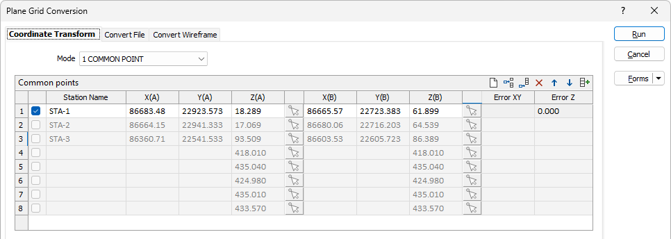
Coordinate Transform
Common points (grid list)
Underground laser scans typically have an arbitrary 0,0,0 origin. Scans are gravity aligned so a rotation around Z with XYZ shift is usual. The scan will include multiple "stations" which have scan coordinates (digitised) and mine grid coordinates (supplied). The translation between grids must be calculated and applied to the point cloud.
You can specify any number of points to arrive at a least square error solution. On each row of the grid, specify the translation, rotation and scale in the X and Y plane, and along the Z axis, for a point in each coordinate system A and B. The Residual Error is shown in the right-most column on each row.
The Mode option allows you to select how many common points you want use in order to perform the conversion - 1, 2, or 3 or more.
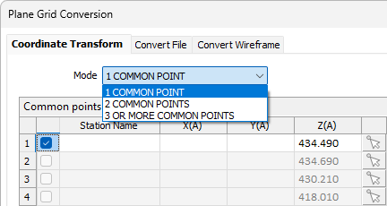
When an option is selected, any points that cannot be applied will become inactive in the grid - for example, all points except the first for the 1 COMMON POINT option.
Use the check boxes to exclude one or more of the available rows from the transformation. Note: An error will be displayed if there are too few points with which to arrive at a solution. For example, if the default 3 OR MORE COMMON POINTS option is selected, a minimum of three unique points must be specified.
Pick Point
![]() Pick Point icons in each row of the Common Points grid, allow you to interactively pick the common points for coordinate systems A and B.
Pick Point icons in each row of the Common Points grid, allow you to interactively pick the common points for coordinate systems A and B.
Clicking on a Pick Point icon will collapse the form and allow a point to be selected:
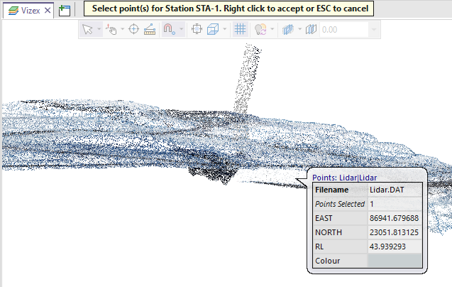
The coordinates of the point you have picked are loaded into the form.
Alternatively, hold down the left mouse button and drag the mouse to select multiple points. The centroid of the points you have selected is calculated and loaded into the form.
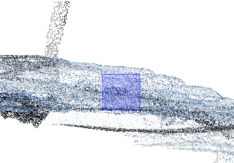
To perform a lasso selection, hold down the SHIFT key as you hold down and drag the left mouse button. In this selection mode, Snapping is temporarily turned off.
Polygon selection is also supported (interactively digitise a new closed string to select the points within it).
Conversion Parameters (From A to B)
Input
In the Rotation field, you can optionally enter a rotation value for the A to B conversion to be used instead of the value calculated by the application.
When a compound (DDD.MMSS) rotation value is entered it must be a valid compound number and take one of the following forms:
|
123 |
The rotation value only has a degrees component. |
|
123.20 |
The rotation value has degrees and minutes components. |
|
123.2040 |
The rotation value has degrees, minutes, and seconds components. |
|
123.204156 |
The rotation value has degrees, minutes, seconds, and decimal seconds components. |
To avoid ambiguity, best practice is to always enter at least 4 digits after the decimal place.
It is also good practice to set-up each grid transformation as a saved form. Transformations can then be performed quickly without having to re-enter the transformation parameters. See Saving.
Use the Scale field to enter a scale for the conversion, if you do not want to use the calculated scale.
In the Z(B)-Z(A) field you can apply a constant Z shift value for Grid A and Grid B to ensure that all Z values are greater than zero. Otherwise, you can use the value calculated by the program.
Calculated
The Rotation field displays the calculated rotation value for the conversion. If you select the corresponding Use check box, the value will be applied to the conversion.
The Scale field displays the calculated scale value for the conversion. Select the Use check box to activate the value for the conversion.
Select the Z Shift check box to enable Z shift value conversion.
The Z(B)-Z(A) field displays the calculated Z shift value for the conversion. Select the Use check box to apply the calculated value to the conversion.
Conversion
The Rotation, Scale and Z(B)-Z(A) fields display the calculated values for the corresponding details, after conversion.
Status
A Residual Standard Deviation (RSD) value is shown when a least squares solution can be arrived at.
Angle Units
Use the drop down list to select the (DDD.MMSS or DDD.DDDD) Angle Units format for the rotation value, which is the angle between the North directions of the grids.
A preview of the results for the configured angle details is displayed.
")
Grid Names
Enter identifying names for the A and B grids for the conversion in the Grid A and Grid B fields.
Coordinate Conversion Test
Use the test grid to enter test points for Coordinate systems A and B and preview the results based on the parameters you have entered. You can enter custom Grid Names for Grid A and Grid B for reporting purposes or accept the default values.
Enter X, Y and Z test coordinates for both grid systems. The conversion values for the To grid will be populated by the calculated values. Error values are also populated with values from the calculation.

Saving
You can save the current values in the Plane Grid Conversion form as a new form using the Save or Save As options from the Forms button. Both features will open the Save Current Values in Open Form As form if saving for the first time.

Use the form to save the values in the form as a set and click OK. The newly created form can be loaded at a later date using the Forms option on the Plane Grid Conversion form. You can edit and delete saved forms using the Manage option.
More information on using and managing forms is contained in Forms.