Image Georeference
![]()
You can also click the Georeference button on the Vizex Image form (on the Home tab or the Vizex tab, in the Layer group, select Display Layers | Image).
In order to display raster images with other spatial data, you first need to align or georeference those images to a map coordinate system. When you georeference a raster image, you assign real-world map coordinates so that it can be viewed and queried alongside other spatial data. The process involves the specification of a series of control points that can be used to link points on the raster image with locations in a spatially referenced dataset.
Once an image has been georeferenced, it can be displayed with other data in that coordinate system. The application supports georeferenced data files from a variety of GIS, Image Processing, and CAD software.
It is also normal to acquire an image with no georeferencing whatsoever, such as a scanned historic map. This kind of image can still be georeferenced, if three or more locations can be identified on the image, and their real-world co-ordinates are known. Such locations are known as georeference control points (GCPs).
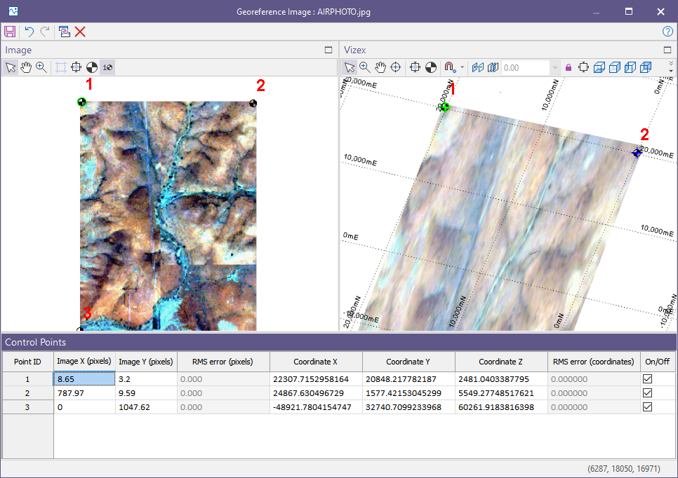
The Georeference Image window comprises two panes:
- Image: Displays the image to be georeferenced.
- Vizex: Optionally displays the current Vizex view as an external coordinate reference, which should cover the same region as the image.
Tools on the local toolbar can be used to add, label, move and delete GCPs, along with tools for manipulating and configuring the Vizex view. In the Vizex pane, Snap Mode is available for precise GCP picks. Beneath the panes is the Control Points list, which lists the image and real-world coordinate values along with their errors.
To add a GCP:
- Click a feature in the Image pane whose location you know. It should be an obvious corner, surveyed structure (e.g. drillhole collar), or map element (e.g. intersecting gridlines).
- Next, supply its real-world coordinate values:
- for an image with no Vizex view, manually enter the values for each GCP.
- for an image with a Vizex view, simply click the corresponding feature in the Vizex pane. Once two GCPs are selected, the panes are geolinked and a preview of the georeferenced image is overlain in the Vizex pane. Adjust the slider to change its transparency.
- GCPs always require 3D coordinates; to georeference an image on an orthogonal plane (plan, cross-section or long section), enter a Section or Elevation value in the Vizex pane and lock the plane. This forces the locked axis to always take the Section or Elevation value.
Only three GCPs are needed for a georeferencing solution. However, adding more will improve its accuracy. Once there are four GCPs, the application will measure the error and predict the real-world coordinates of each GCP. You may optionally disable any GCPs with a large error.
When you georeference an image, the application creates headers for Mapinfo and ArcGIS along with a Micromine header. Headers have the same name as the image, with a GRF (Micromine), TAB (Mapinfo) or xxw (World file) extension. For a World file, xxw represents the first and last letter of the original image extension followed by a w, for example tfw for a tif image.
Georeferenced images created in the application do not include coordinate system tags. If you are a GIS user, you should manually tag the image with its coordinate system name within your GIS application.
The application does not rectify image defects like folds in a scanned map or geometric distortion in an airphoto. If your image is distorted, you must rectify it, which also georeferences it, in a GIS or image processing application.
To georeference an image:
- Use one of the following methods to select the image:
- On the File tab, in the Image group, select Image | Image Georeference.
- On the Home tab or the Vizex tab, in the Layer group, select Display Layers | Image.
- In the Image pane at the left-hand side of the window, make sure the Select tool is active on the toolbar and use the mouse to digitise a GCP as accurately as possible. A labelled control point is added. Use the Toggle Point Indices option on the toolbar to toggle point labels off if necessary.
- A corresponding control point is added to the scene in the Vizex pane. If you cannot see the point, you may need to geolink or align the two panes.
- Click in the Vizex pane to pick a 3D coordinate for the image point. A circle and cross are used to depict each control point/reference point pairing.
- As an alternative to Step 4, enter known coordinates for the control point in the Coordinate X and Coordinate Y (and for a 3D image, Coordinate Z) fields in the Control Points grid.
- To select or move a point in either pane:
- Hover your mouse over the point.
- Click to select the point.
- Click and drag the point to move it.
In the Select Input File dialog, select an image file type and navigate to the location of the image file. Click Open.
In the Vizex Layer Display pane, right-click on an Image layer and select Edit Georeference.
In the Load Image form, click the Georeference Image button.
Note: If the image is already loaded in Vizex, the layer is hidden while the Georeference Image window is open.
Automatic corner points are added when a georeference file without control points is encountered.
The coordinates of the digitised reference point are added to the Control Points grid where they may be modified if necessary:
A reference point is added to the Vizex pane at that location.
In the Vizex pane, a change in mouse cursor is used to differentiate between a control point and a reference point.
Control Points
In 2D georeferencing one of the coordinate values (usually Z) is constant.
In 3D georeferencing all three values may vary. If left blank, Z coordinate values will default to 0 so that they do not need to be manually set when working in 2D.
If you are georeferencing a 2D image, two or three points can be digitised and four (Pixel X, Pixel Y, Coordinate X, Coordinate Y) coordinate columns are displayed for each point.
In 3D georeferencing, it is vital to know the coordinates of locations that fall on the plane of the image. Drillhole collars, specific downhole intersections, and intersections with underground mine workings are suitable sources of these locations and can be loaded in the Vizex pane when picking reference points.
If you are digitising a 3D image, three or more points can be digitised and five (Pixel X, Pixel Y, Coordinate X, Coordinate Y, Coordinate Z) coordinate columns are displayed for each point.
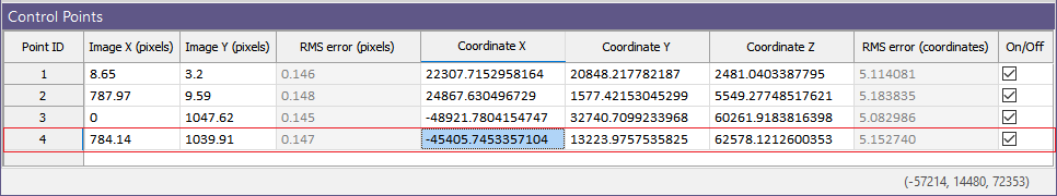
If a fourth point is digitised, then a Root Mean Square (RMS) error is also shown which provides an indication of how consistent the transformation is between the specified control points. To include or exclude a control point based on its goodness of fit, simply toggle the On/Off switch at the end of the data row.
If there are insufficient control points to fully georeference an image in 3D the following message is displayed: "If you proceed, rotation will be unsupported and the image will be given a constant Z value. Do you wish to exit anyway?"
The state of the On/Off check boxes are written as metadata to the GRF georeference file and an icon is used to show which control points (in the Image pane and the Vizex pane) are currently excluded:
![]()
To define a specific section, for example, Looking North, use the Display Limits tool on the Vizex pane toolbar (See Tools below).
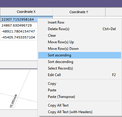
You can use the options on the right-click menu to manage the rows in the grid:
Notes:
GIS headers cannot support a 3D orientation and the images will be projected into a plan view instead. If the original 3D image is steeply inclined this can make the GIS version look heavily distorted. Nevertheless, it is a true representation of the 3D geometry.
Note that the Custom 2D Source option cannot be used to drape an image over a wireframe and should only be used when you want to register an image by defining the coordinates of the top left pixel and the pixel size.
In the case of a 2D image, a MapInfo TAB file and an Arcview World file are written to the folder containing the image file. There are two exceptions however:
- World or TAB files won't be generated when the image is in 3D, and when the image is rotated by more than a pixel or two.
- In the case of a 3D image, a Georeference file (*.GRF) is created. These georeference files are generated automatically when you generate a screenshot of the current view in Vizex, or when you select the Plot as image option when generating a plot file. GRF Georeference files have no issues with rotation.
Tools
The following options are provided on the shared toolbar in the Georeference Image window:
|
|
Click Save to save the listed control points and the georeferenced image layer. |
|
|
Click Undo to undo the edits you have made in the Georeference Image window. |
|
|
After an Undo, click Redo to redo the edits you have made in the Georeference Image window. |
|
|
Click Geolink Windows to synchronise zooming and panning in the Image pane and the Vizex pane. |
|
|
Click Delete to delete the selected control points. |
Image pane
The following toolbar options are provided on the Image pane:
|
|
Use the Select tool to create, select, or move a control point. |
|
|
Use the Pan tool to drag the Image in the direction you move the cursor. If both panes are geolinked, then both panes are panned simultaneously. |
| If you hold down the CTRL key, you can use the Pan tool to zoom in and out. Drag the cursor down to zoom in, or up to zoom out. | |
|
|
Use the Zoom tool to zoom using the left mouse button. To zoom into a region, drag a zoom box. To zoom out, use CTRL + left mouse click. |
|
|
Click the Show Guides button to show (make them prominent) or hide the guides when moving the mouse in the Image pane. |
|
|
Use the View All tool to zoom to the full extents of the image. |
|
|
Click Zoom to selection to position the selected point in the centre of the window (without changing the zoom level). Note: In the Control Points grid, you can double-click on any control point row to zoom to that selected point. |
|
|
Click Toggle Point Indices to toggle control point labels on and off. |
Vizex pane
The following toolbar options are provided at the top of the Vizex pane:
|
|
Use the Select tool to select or move a control point or reference point. |
|
|
Use the Zoom tool to zoom using the left mouse button. To zoom into a region, drag a zoom box. To zoom out, use CTRL + left mouse click. |
|
|
Use the Pan tool to drag the Vizex scene in the direction you move the cursor. If both panes are geolinked, then both panes are panned simultaneously. |
| If you hold down the CTRL key, you can use the Pan tool to zoom in and out. Drag the cursor down to zoom in, or up to zoom out. | |
| If you hold the Shift key down, you can use the Pan tool to rotate the Vizex scene in 3D. | |
|
|
Use the Seek tool to select a point to be the centre of rotation. For triangles, polygons and block faces, change the view by holding down the CTRL key. |
|
|
Use the View All tool to zoom so that the whole image is visible. |
|
|
Click Zoom to selection to position the selected point in the centre of the window (without changing the zoom level). Note: In the Control Points grid, you can double-click on any control point row to zoom to that selected point. |
|
|
Click the Snapping Mode option to toggle the current Snapping on and off. Alternatively, you can toggle the snap mode on and off using the S shortcut key. |
| To cycle through Snap modes, use the SHIFT + S key. Point, Line, Grid, Intersection, Surface, and Perpendicular snapping options can be selected from the tool menu. Note that Snap mode only applies to those display layers that have a 'Snappable' Snap status. | |
|
|
On the Vizex | Section tab, in the Section group, click Align Planes to align the Vizex view with the current image georeference. |
|
|
On the Home tab or the Vizex tab, in the Section group, click Enable Clipping to enable or disable clipping. Use the Display Limits function to modify the size of the clipping window. |

|
|
| For orthogonal views, this box shows the Section or Elevation value. To edit, type a new value and then press the Enter key or click on the Clip View button. | |
| The Lock Plane tool is useful when you want to lock the elevation while making 3D picks to georeference a 2D image. | |
|
|
Use the Display Limits button to set the limits of the graphic display. You can define Orthogonal, Transform, or 3D display settings in the Display Limits. |
|
|
On the Vizex tab, in the Viewpoint group, select from the Plan, Looking Up, Looking East, Looking West, Looking North and Looking South buttons to define an orthogonal view of your data. |
|
|
On the Vizex tab, in the Working Plane group, click Show/Hide Plane to toggle the Auto-Working Plane on and off. See: Coordinate Grid Settings |
|
|
On the Vizex tab, in the Grid group, select Options to open the Coordinate Grid Settings form. See: Coordinate Grid Settings |
| Click the Depth Testing button to toggle the drawing order between 3D position order and Drawing (layer) order. | |
| Use the Transparency slider to specify the intensity of the image. The visibility of the layers underneath the image will be determined by the degree of transparency you select. | |
|
|
You can also:
| Use a number of Georeference Hot Keys. | |
|
|
Click the Maximise icon at the top right of a pane to maximise that pane. |
|
|
Click the same icon to Restore the side-by-side layout of the Image and Vizex panes. |
See Also: Fence Image Registration