Fence Image Registration
The application has the ability to georeference (or register) images in 3D, including scans of paper plans or maps. However, this assumes the image represents a single plane, which is frequently not the case.
Fence Image Registration allows a single image to be draped onto multiple, adjacent vertical planes, rather than onto a single vertical plane.
![]()
You will be prompted to select the image you want to register.
Examples of a fence image are a "section" that bends at every (vertical) drillhole, or a seismic line (or string) that bends because of surface obstructions. In both cases, a single image needs to be draped onto multiple, adjacent vertical planes, rather than onto a single vertical plane.
The image you select is opened in the Fence Image Registration window.

Vertical Scale
When the Fence Registration window is opened, and you are registering an image for the first time, your first task is to define the vertical scale. There are two ways to set the vertical scale:
Elevation Difference
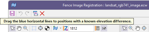
By default, you will be prompted to drag the blue horizontal lines in the Image window to positions with a known elevation difference:
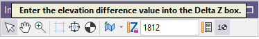
You will then be prompted to enter the elevation difference (in world units) into the Delta Z box on the Image window toolbar:
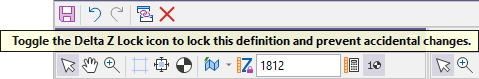
Once you have defined the elevation difference, you can click the Delta Z Lock toggle button to lock the vertical scale (elevation difference) you have defined and prevent accidental changes.
Calculate Vertical Scale
If the image does not have any Z (elevation) information, you will not be able to define the elevation difference (above). In this case the best that you can do is assume that Y pixel size = X pixel size (in grid units). The first step is to define the location of the fence angles (horizontal registration). Then use the Calculate Vertical Scale button to make the Y pixel size = Average X pixel size (in grid units).
![]()
Control Points
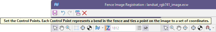
Once the vertical scale has been defined, you can then set the control points that define the vertex of each vertical plane.
Begin by setting control points to define the start and end of the fence.
You can then use the Calculate Bend Points tool on the Image window toolbar to set control points that define the location of the folds (or bends) along the fence.
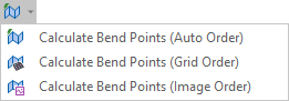
Calculate Bend Points
There are different ways to define the coordinates of the intermediate (bend) points. The option you choose will depend on the real-world (string or drillhole) data you are mapping to the image.
|
Calculate Bend Points |
Description |
|---|---|
|
Auto |
Control points are ordered based on their distance from the first valid control point in the grid. |
|
Grid |
Control points use the same order as displayed in the grid. |
|
Image |
Control points are ordered based on their Image X (pixels) value. |
Each time a control point is moved in the Vizex window, the image coordinates for the whole wireframe are recalculated to evenly spread the image across each section of the fence. Adjustments can be made to the image coordinates in the Image window or the Control Points grid.
Note that:
- Control points determine the segment boundaries of the fence.
- User coordinates determine the vertex positions of the fence,
- Image coordinates control which sections of the image are mapped to each segment of the fence.
Pixel Size X and Pixel Size Y
The Pixel Size (X) and Pixel Size (Y) values of a control point (in the Control Points grid) are the size of a pixel in the fence section that is defined by the control point and the previous control point.
Image X (pixels)
The X pixel value of each hole collar or string vertex on the original scanned section. This is used when splitting the section image into slices, and for defining the Georeference Control Points (GCPs).
Image Y (pixels)
Not used in the Input file, but required in the Output file which uses the Input file as a structure template
Tools
The following options are provided on the shared toolbar in the Fence Image Registration window:
|
|
Click Save to save the control points and the vertical scale you have defined to a fence image registration file with a . mmireg file extension. |
|
|
Click Undo to undo the edits you have made in the Georeference Image window. |
|
|
After an Undo, click Redo to redo the edits you have made in the Georeference Image window. |
|
|
Click Geolink Windows to synchronise zooming and panning in the Image pane and the Vizex pane. This option is enabled by default. |
|
|
Click Delete to delete the selected control points and clear those values in the grid Control points that contain blank values are excluded from the rendered fence wireframe. |
Image window
The following toolbar options are provided in the Image window:
|
|
Use the Select tool to create, select, or move a control point. |
|
|
Use the Pan tool to drag the Image in the direction you move the cursor. If both panes are geolinked, then both panes are panned simultaneously. |
|
|
If you hold down the CTRL key, you can use the Pan tool to zoom in and out. Drag the cursor down to zoom in, or up to zoom out. |
|
|
Use the Zoom tool to zoom using the left mouse button. To zoom into a region, drag a zoom box. To zoom out, use CTRL + left mouse click. |
|
|
Click the Show Guides button to show (make them prominent) or hide the guides when moving the mouse in the Image pane. |
|
|
Use the View All tool to zoom to the full extents of the image. |
|
|
Click Zoom to selection to position the selected point in the centre of the window (without changing the zoom level). Note: In the Control Points grid, you can double-click on any control point row to zoom to that selected point. |
|
|
Use the Calculate Bend Points drop-down menu to choose how the 3D coordinates of intermediate control (bend) points are calculated. See Calculate Bend Points (above) |
|
|
Click the Delta Z Lock button to lock the vertical scale you have defined. See Delta Z below. |
|
|
When you have interactively defined two positions with a known elevation difference, enter the elevation difference in the Delta Z box. See Elevation Difference above. |
|
|
|
|
|
Click the Calculate Vertical Scale button to make the vertical scale the same as the (average) horizontal scale. |

Vizex window
The following toolbar options are provided in the Vizex window:
|
|
Use the Select tool to select or move a control point or reference point. |
|
|
Use the Zoom tool to zoom using the left mouse button. To zoom into a region, drag a zoom box. To zoom out, use CTRL + left mouse click. |
|
|
Use the Pan tool to drag the Vizex scene in the direction you move the cursor. If both panes are geolinked, then both panes are panned simultaneously. |
|
|
If you hold down the CTRL key, you can use the Pan tool to zoom in and out. Drag the cursor down to zoom in, or up to zoom out. |
|
|
If you hold the Shift key down, you can use the Pan tool to rotate the Vizex scene in 3D. |
|
|
Use the Seek tool to select a point to be the centre of rotation. For triangles, polygons and block faces, change the view by holding down the CTRL key. |
|
|
Use the View All tool to zoom so that the whole image is visible. |
|
|
Click Zoom to selection to position the selected point in the centre of the window (without changing the zoom level). Note: In the Control Points grid, you can double-click on any control point row to zoom to that selected point. |
|
|
Click the Snapping Mode option to toggle the current Snapping on and off. Alternatively, you can toggle the snap mode on and off using the S shortcut key. |
|
|
To cycle through Snap modes, use the SHIFT + S key. Point, Line, Grid, Intersection, Surface, and Perpendicular snapping options can be selected from the tool menu. Note that Snap mode only applies to those display layers that have a 'Snappable' Snap status. |
|
|
Click the Align View button to align the Vizex view with the current image georeference. |
|
|
Click the Clipping button to enable or disable clipping. Use the View | Display Limits function to modify the size of the clipping window. |
|
|
|
|
|
For orthogonal views, this box shows the Section or Elevation value. To edit, type a new value and then press the Enter key or click on the Clip View button. |
|
|
The Lock Plane tool is useful when you want to lock the elevation while making 3D picks to georeference a 2D image. |
|
|
Use the Display Limits button to set the limits of the graphic display. You can define Orthogonal, Transform, or 3D display settings in the Display Limits. |
|
|
Select from the Plan, Looking Up, Looking East, Looking West, Looking North and Looking South buttons to define an orthogonal view of your data. |
|
|
Click the Auto-Working Plane button to toggle the Auto-Working Plane on and off. See: Coordinate Grid Settings |
|
|
Click the Grid Settings button to open the Coordinate Grid Settings form. See: Coordinate Grid Settings |
|
|
Click the Depth Testing button to toggle the drawing order between 3D position order and Drawing (layer) order. |
|
|
Use the Transparency slider to specify the intensity of the image. The visibility of the layers underneath the image will be determined by the degree of transparency you select. |
|
|
|

You can also:
|
|
Use a number of Georeference Hot Keys. |
|
|
Click the Maximise icon at the top right of a pane to maximise that pane. |
|
|
Click the same icon to Restore the side-by-side layout of the Image and Vizex panes. |