Georeferenced Images
Plan Views in Micromine Geobank support the display of georefrenced background images. The following sections contain detailed information on configuring and using georeferenced images with Plan Views.
Georeferencing
Georeferenced images are a digital image containing metadata associated with specific Coordinate Reference System (see Coordinate System Editor ). The information within the georeferenced image enables users to determine where every point in a view is physically located on Earth.
Micromine Geobank will scan the configured Plan View Images folder (see Options) for supported file formats with Easting and Northing georeference coordinates which match the Plan View and display them in the background.
If more than one image is matched, they will all be overlaid in the background. Files will be displayed in alphabetical order, so the first alphabetically will be under the other images and the last on top. In this instance, the slider will be applied to all layers equally.
Currently, supported image types are:
-
.tiff , .tif
-
.jp2 , .j2k
-
.jpg , .jpeg
-
.png
Files in the .jpg, .jpeg and .png format require a Micromine Origin format georeferenced metadata file (.grf ) of the same name in order to be matched to the Easting and Northing of the Plan View and be displayed. Files of this type will not be considered georeferenced by Micromine Geobank without a matching .grf file.
Micromine Geobank will use the .grf file of the same name for georeference of .tiff, .tif, .jp2 and .j2k files, if there is one. If no matching .grf file exists, the application will use the metadata stored in the file itself.
It is recommended to test your files before committing too much effort, as georeferenced image files can be created in a large variety of software programs, with varying results.
Note: Images must be stored in the Plan View Images Folder selected in the Home | Options and Configuration Settings form. See Image Storage.
Micromine Geobank 23.0 uses a very simplistic approach to selecting the images to display in a plan view:
-
When the Plan View is executed or redrawn, if Show Background Images is selected, the area displayed in the Plan View (defined by the top-left and bottom-right coordinates) is noted. These coordinate values may be Easting-Northing, Lat-Long or cartesian pairs.
-
These coordinates are compared to similar values from the metadata for the available georeferenced images - i.e. at area (potentially rotated) which the image covers. Again these may be Easting-Northing, Lat-Long or cartesian pairs.
-
Images or portions of images for which an overlap is found are then displayed in the Plan View as background images.
Note: This simplistic approach was adopted to make the feature available in Micromine Geobank2023, but further refinements are planned to address the situation where incorrect overlaps are found and thus incorrect images are shown - for example North vs South or Zone vs Zone overlaps.
Please notify our support team if you encounter any issues when using this feature in Micromine Geobank 2023.
Image Storage
For images to be displayed in the background for Plan Views, they must be stored in the folder selected in the Folder Locations section of the Plan Views page on the Options form.
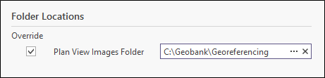
Make sure the folder set is the location of the georeferenced images to be displayed. With this configured, you can set the default display behaviour for the images within the Plan View Property Editor.
Configuring Image Display
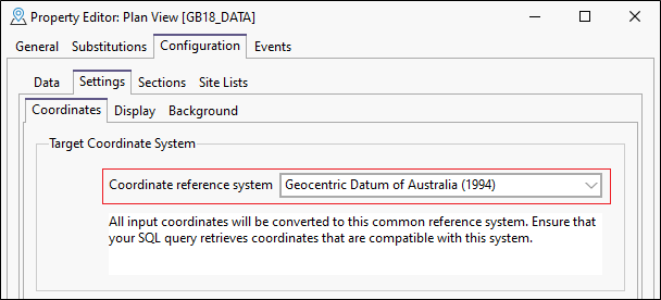
When creating or modifying a Plan View, using the Plan View Property Editor, you can set the default behaviour for the display of georeferenced images on the Configuration | Settings page.
On the Coordinates tab, the Coordinate reference system must be set to the equivalent system contained in the georeferenced image to be displayed for the Plan View.
In the Display tab of the Property Editor, you can configure the point symbology, line styles, colours, and the font characteristics of the plan view annotation if required. See Display for more details.
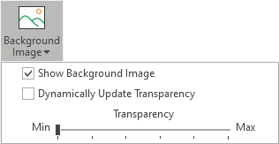
The Background tab of the Settings page sets the default behaviour of background images for the plan view. They can be modified from within the plan view using the Background Image menu in Tools.
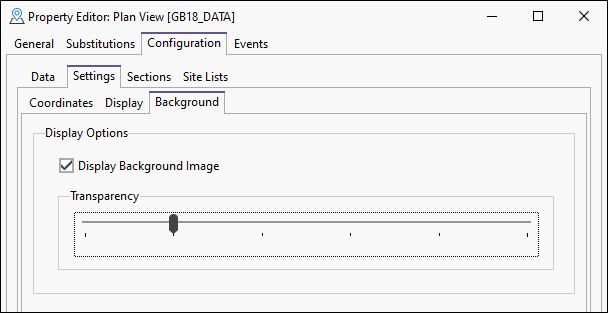
Display Background Image
Select this option to display any applicable georeferenced image for the plan view.
Micromine Geobank will scan the configured Plan View Images folder (see Options) for supported file formats with Easting and Northing georeference coordinates which match the Plan View and display them in the background.
Transparency
Use the Transparency slider to set the default transparency level for the background image display in the plan view. If more than one image is overlaid in the background, the Transparency level applies equally to all layers.
When the Plan View has been configured for display, you can execute it using the method outlined in Plan View. Once displayed, there are tools that can be used to place and move the configured background image.
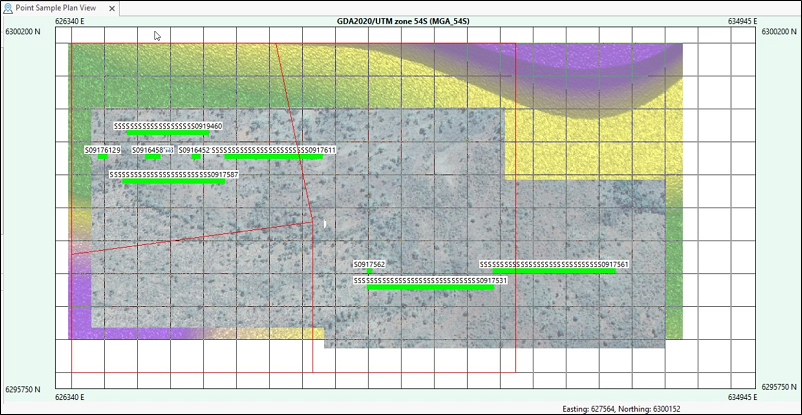
Image Tools
The Tools for the Plan View feature a number of options used to place and move the georeferenced background image displayed.
Background Image
Select an option from the Background Image menu to display a georeferenced image from the configured Plan View Images Folder.
The Dynamically Update Transparency check box determines whether the transparency level for the georeferenced background image is dynamically updated as the Transparency slider is adjusted. With this option unchecked, the transparency level will take effect when the slider is stopped.
You can also set the Transparency level of the displayed image. The default transparency value may have been configured for the Plan View, but you can use the slider to change the current transparency level of the display.
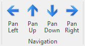
Navigation
Use the arrows in the Navigation section to Pan the grid for the Plan View display, one grid unit per click in the selected direction. Any included background image will also pan with the grid; ensuring the correct location of each point is retained in the display.
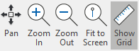
There are also mouse-behaviour changing options such as Pan, Zoom In, Zoom Out, Fit To Screen, as well as the option to show or hide the grid.
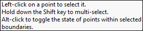
There are also some useful tips shown on the screen:
There are various Export options:
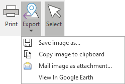
The Save image as… option saves the main image area, including the grid and coordinates system.
The View in Google Earth option creates a .kml file of the points and displays them in Google Earth.
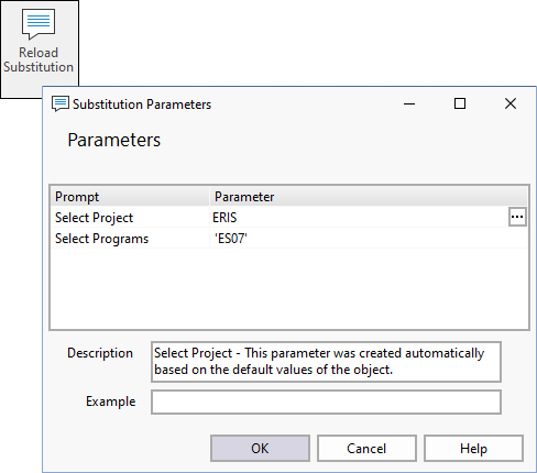
Reload Substitutions
The Reload Substitutions option displays the Substitution Parameters screen, enabling either a reload of current data or the selection of new data for display.