Settings
Coordinates
On the Configuration | Settings | Coordinates page of the Plan View Property Editor, select a target coordinate system.
Target Coordinate System
All input coordinates will be converted to this common reference system. You must ensure that the SQL query you setup on the Data page retrieves coordinates that are compatible with this system. Additionally, only georeferenced images of the same coordinate reference system (CRS) will be enabled for display in the plan view.

More information on Coordinate Reference Systems can be found in Coordinate Transformation Configuration and Coordinate System Editor.
Use transformation grids for datum conversions
Select this option if the relevant transformation grids for your area are available via the datum shift tables. The use of a transformation grid is recommended in cases where a high degree of accuracy is required. The default method (abridged Molodensky) will be used if a suitable transformation grid cannot be found.

Display
On the Configuration | Settings | Display page of the Plan View Property Editor, you can configure the size and colour of Points and Lines for the plan view.

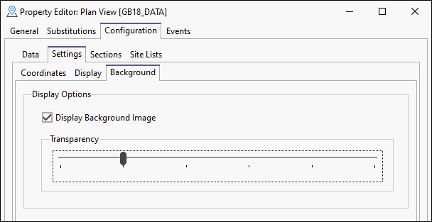
Background
On the Configuration | Settings | Background page of the Plan View Property Editor, you can configure the behaviour of background images for the plan view. These options set the default behaviour in the plan view. They can be modified from within the plan view using the Background Image menu in Tools.
Display Background Image
Select this option to display any applicable georeferenced image for the plan view.
Micromine Geobank will scan the configured Plan View Images folder (see Options) for supported file formats with Easting and Northing georeference coordinates which match the Plan View and display them in the background.
Note: Images must be stored in the configured Plan View Images folder as well as contain matching georeference data either in the file or in a .grf file of the same name.
Transparency
Use the Transparency slider to set the default transparency level for the background image display in the plan view. If more than one image is overlaid in the background, the Transparency level applies equally to all layers.
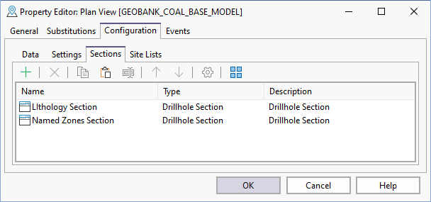
Sections
Use the Configuration | Sections page of the Plan View Property Editor to setup the columns for different sections. See Sections .
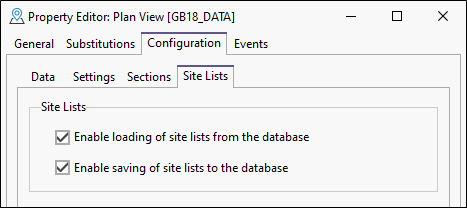
Site Lists
Use the Configuration | Site Lists page of the Plan View Property Editorto configure the Site Lists settings for the Plan View.
In Micromine Geobank, a POINT ORDER column is added to the GB_SITE_LIST table. This means you can load or create a site list in the plan view and use it to generate a section view. You may however, choose not to enable the ability to load and save site lists into the plan view.