Create Surface
![]()
Grid
Use the drop-down to select an Output Grid.
Tip: In the Grid Selection pane, you can right-click on the Grids node (or a folder) to Add a New (empty) grid.
Surface
The grid creation process will use the triangulations and the shapes currently visible in the Design Window to set the default extents of the grid. Use the drop-down to choose whether the process will take the top-most (Top) or the bottom-most (Bottom) Z value encountered for each XY point.
Precision
Accept the default or use the drop-down to select a (Fast, Accurate) precision mode.
Accurate is the default mode of precision. The gridding algorithm will attempt to maintain precision for small regions. This is achieved by sampling an area that is the size of the data extents. Additional data points outside the selected region are then ignored when creating the grid.
Fast may be preferable when a large region (relative to the size of the data extents) is selected.
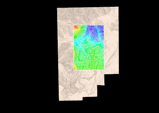
Rainbow Colours
Rainbow colours provide an intuitive colours scheme and the perception of depth for your grid surface. The option to turn the rainbow colouring on and off is provided. When comparing grids, you might choose to set your own colouring for the grids, for example.
Fill Holes
Select the Fill holes check box to fill any holes created by the process.
Triangulate
Select this check box to create a triangulation from the data extents in addition to a grid surface. When this option is selected, a Triangulation Options group is shown in the dialog.
Note that the Data Extents group (below) is no longer visible, however a scroll bar allows you to scroll down to set the data extents.
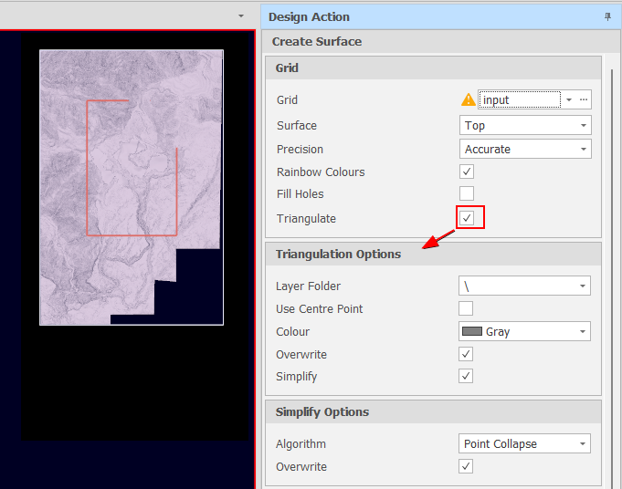
Triangulation Options
The following parameters are available when the Triangulate check box has been selected in the Grid group:
Layer Folder
Accept the default Layer folder or choose a sub folder for the generated triangulation,
Use Centre Point
Select this check box to triangulate from the centre point rather than the grid reference point.
Colour
Click on the Colour cell to choose between theme colours, standard colours or select a colour from a chosen palette.
Overwrite
If a triangulation of the same name (set when you set the Grid name) already exists in the specified folder, select this check box to overwrite it.
Simplify
Select this check box to set options to simplify the generated triangulation (recommended).
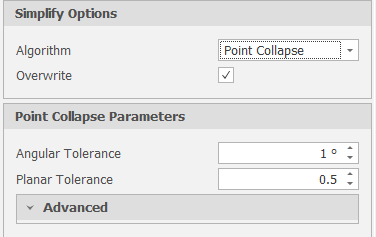
When the Simplify check box option is selected, a Point Collapse algorithm is applied to the triangulation process. This is currently the only option.
Select the Overwrite check box to overwrite the specified Output triangulation layer. If you choose not to overwrite the layer, an incremental number suffix is used to write to a new copy of the specified Output layer.
Point Collapse Options
Accept the defaults or adjust the Angular Tolerance and Planar Tolerance values.
-
Angular Tolerance (an angle in degrees, defaults to 1)
-
Planar Tolerance (a distance in metres or feet if Imperial, defaults to 0.5)
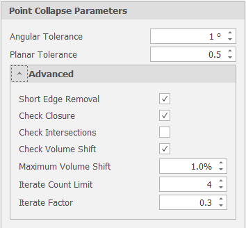
Advanced
Use the drop-down to set advanced point collapse options:
-
Short Edge Removal (Boolean - defaults to True)
-
Check Closure (Boolean - defaults to True)
-
Check Intersections (Boolean - defaults to True)
-
Check Intersections (Boolean - defaults to True)
-
Maximum Volume Shift (Percentage. Must be greater than or equal to 0% and less than or equal to 100%)
-
Iterate Count Limit (Must be greater than or equal to 1)
-
Iterate Factor (Must be greater than 0 and less than 1)
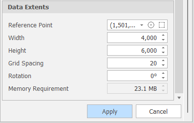
Data Extents
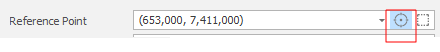
Reference Point
Click the Set Reference Point icon to interactively digitise a reference point in the Design Window, then drag an extent rectangle to set the width and the height of the grid:
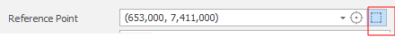
Alternatively, click the Data Extents icon to set the reference point, width and height of the grid automatically based on the design elements that are currently visible in the Design Window:
Width
The width of the grid is calculated automatically based upon the current data extents, You can enter a value or use the increment controls to adjust the value up or down.
Height
The height of the grid is calculated automatically based upon the current data extents, You can enter a value or use the increment controls to adjust the value up or down.
Grid Spacing
The granularity of the grid is calculated automatically based upon the current data extents, You can enter a value or use the increment controls to adjust the value up or down.
Rotation
Grids are created in Plan View, however you can specify a rotation value to display the grid in a different orientation.
Memory Requirement
An indication of the memory requirement needed to process and store the grid. A large grid spacing will be fast to compute but will produce a coarser result, while a small grid spacing will be slower to compute but will produce higher resolution.
Apply
Finally, click Apply to generate the grid (and optionally a triangulation). Check that the result of the operation is what you expect. If necessary, use CTRL+Z to undo.