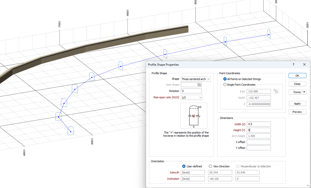
Profile Shape
![]()
- If there is no active layer, or the active layer is not a String layer, you will be prompted to open or select a String layer as the active layer.
- The mouse cursor changes to a square so that you can select a point that defines the location of the profile shape.
- In the Profile Shape Properties form, set the properties of the profile shape:
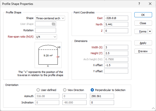
When the Profile Shape Properties form is opened after selecting the profile position:
- If the profile was placed on a string, Perpendicular to selection is selected as the default orientation and the Azimuth and Inclination of the profile are calculated.
- If the profile was not placed on a string, User-defined is selected as the default orientation.
- If User-defined is selected as the orientation and the Azimuth and Inclination fields are not blank when the form is closed, the next time the form is opened, the default orientation will be User-defined.
Profile Shape
Shape
Choose the shape the extrusion will take. With the exception of the Trapezoids and the Three-centred Arch, the shapes are self-explanatory. The dimensions that you must enter in the adjacent prompts are also displayed in the Preview window below the Shape list box.
Trapezoid 1 has its smaller dimension to the top of the display, which you enter in the Top(T) prompt. Trapezoid 2 has its smaller dimension to the bottom of the display, which you enter in the Bottom(B) prompt.
User shape
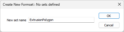
If you have selected User as the shape of the extrusion, double-click (or click on the Forms icon) to select the form set that contains the parameters of the user-defined shape. To create a form set, type a new set name, and then press F4 to create the form set.
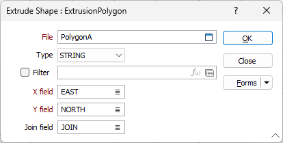
In the Extrude Shape form, specify the file and fields containing the X and Y coordinates that define the shape and optionally apply a filter to restrict the process to a subset of the records in the file.
If you want to load multiple shapes at the same time, you can also specify a Join field.
The shape of the profile appears in the panel in the centre of the main form and is altered when you enter or modify the dimensions. The position of the profile with respect to the string is also shown.
Rotation
Enter a value (0 to 360°) if you want to rotate the profile shape. Use positive or negative values to rotate in a clockwise or anti-clockwise direction.
Rise-span ratio and Height
A Rise-span ratio value and a Height (H) value are used to calculate the curve and the height of the arch when you select either Circular arch or Three-centred arch as the profile shape.
Note that the Height parameter is disabled when Elevation Control is turned on.
You also have the option to enter a Nominal width (W). When the function runs, the Width is calculated from the sidewall polygon. However the profile diagram requires a nominal width to provide a realistic representation of the shape. The default value is the Height.
The ratio is defined as:
h0 / x
where
h0 is the arch height
x is the width of the profile shape
If you are specifying a Custom ratio, a Rise span ratio value can be specified under the Dimensions group (see below).
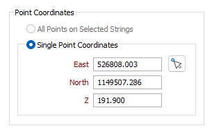
Point Coordinates
The All Points on Selected Strings option can be selected where a string or strings have been selected prior to executing the Profile Shape tool.
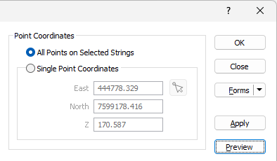
Using the Profile Shape tool in all points mode will create the configured profile shape at every point along the selected string/s.
Where no string has been selected, the Single Point Coordinates option is automatically selected and the coordinates of the point you have digitised in the display are shown here. If necessary, you can edit the Easting, Northing and Z coordinates to adjust the location of the shape. You can also click the Pick from Vizex button to interactively select a point to fill the Profile Shape single point coordinate settings.
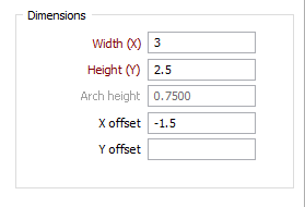
Dimensions
Width (X)
Enter the Width labelled as X in the panel showing the shape display. Optionally, double-click to select the name of a field containing Width values in the string file. The values in this field will be used to control the width of the extrusion.
Height (Y)
Enter the Height labelled as Y in the panel showing the shape display. Optionally, double-click to select the name of a field containing Height values in the string file. The values in this field will be used to control the height of the extrusion.
Arch height / Rise span ratio
You can enter an Arch height value when the Arch Height option is selected in the Rise-span ration drop-down box (see above). If you select a predefined Rise-span ratio, the Arch height is calculated and displayed as a read-only field.
You can enter a Rise span ratio value when the Rise span ratio option is selected in the Rise-span ration drop-down box.
If you are specifying a Custom ratio for the Circular arch, the value you specify must not be greater than 0.5.
Top (T)/Bottom (B)
If you select one of the trapezoids, enter a value for the narrower dimension in the Top or Bottom prompt (the prompt changes according to which of the trapezoid shapes you have chosen).
The shape and dimensions of the wireframe profile appear in the panel in the centre of the form. The position of the profile with respect to the string is also shown.
X and Y offsets
Enter the distance the extrusion will be offset from the string in the X and Y directions. If you also enter the name of a field containing offset values in the adjacent response, this value will be used when values are missing from records in the string file.
Optionally, double-click to select the names of the fields containing X and Y Offset values in the string file. The values in these fields will be used to control how the extrusion is offset.
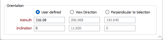
Orientation
User-defined
Select this option to define the plane of the profile shape by entering an Azimuth value and an Inclination value.
If the Azimuth and Inclination user-defined values are left empty, AUTO orientation and inclination values are used. This will essentially set all profiles with the inclination and orientation of the segment on which they are placed. If a profile is located at the node of the string between two segments with different orientations, it will then be placed in the orientation of the bisector of those segments (this applies for Inclination and Azimuth).
View direction
When you select this option, by default the plane of the profile shape is the plane of the current view. You can accept the defaults or enter values to change the Azimuth and Inclination of the plane of the current view.
Perpendicular to selection
When you select this option, snapping is enabled to ensure that the selected point lies on a segment of the selected string (or on the vertex of the selected string). The plane of the profile shape will be perpendicular to the string.
Azimuth
The Azimuth coordinates are automatically populated for each Orientation option and can be modified where valid.
Inclination
Inclination coordinates, like Azimuth values are automatically populated for each Orientation option and can be modified where valid.
Run
Click the Run button to generate the profile shape. You can adjust the parameters and add multiple profile shapes to the display while the form is open. When you have finished adding profile shapes, click Close to close the form.
Forms
Click the Forms button to select and open a saved form set, or if a form set has been loaded, save the current form set.
Manage
To save the types, attributes and names you have defined and re-use them in other functions, click the Manage button to create a form set or load an existing form set.
Save
Click Save to save your changes as the default form set.
Save As
Click Save As to save your changes as a new form set.
Reset
Click Reset to clear the form of all values and reset the form to its default state.