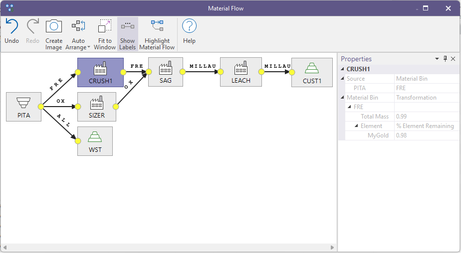
Material Flow Graph
The Material Flow Graph is displayed when you click the Material Flow Graph button, on the Sources and Destinations tab of the Material Flow Optimisation form.
Properties
Click on a node to view the (read-only) properties of that node:
Tools
Use the tools on the ribbon to visualise the connections between the material flow nodes and modify the display.
|
|
Click Undo (CTRL + Z) and Redo (CTRL + Y) to undo and redo (revert the undo of) the last action. |
|
|
Click to generate an image of the Material Flow Graph. You will be prompted to navigate to a Save folder location. The output image file format is PNG. |
|
|
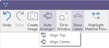
Select an option to Auto Arrange the nodes by aligning the Top or Centre of each node.
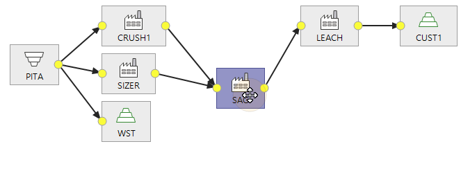
You can also use the mouse to click and drag a node to interactively adjust its position and connectors. This can be used to temporarily clarify the layout of the diagram, however the adjusted layout is not remembered and is reset once the material flow graph window is closed.
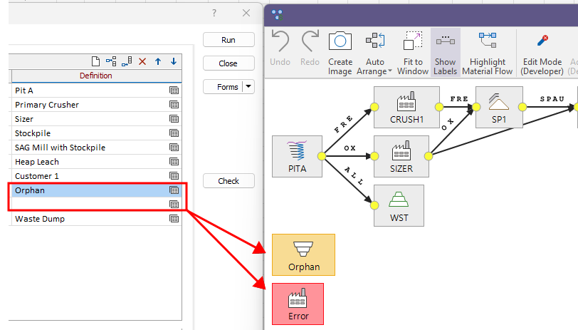
Note that a warning or an error will be flagged for invalid nodes. In this example, one of the nodes defined on the Sources and Destinations list is an orphan, i.e. is not connected to the rest of the network (warning = orange), while the other node has no definition (error = red) :
|
|
|
Click Fit to Window to fit the Material Flow Graph to the window. |
|
|
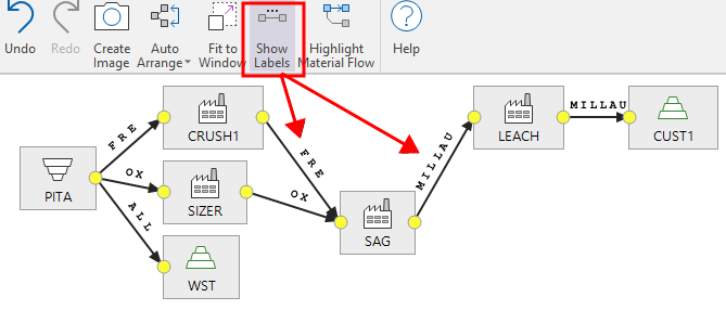
Click Show Labels to toggle the display of labels on and off:
|
|
|
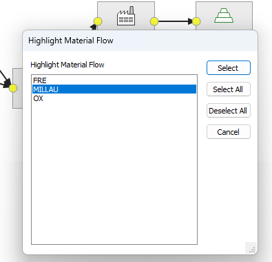
Click Highlight Material Flow to highlight the Material Flow Graph by selected material bin(s). Use the mouse with the CTRL or SHIFT key to select multiple bins. You can also click Select All or Deselect All before finalising your selection:
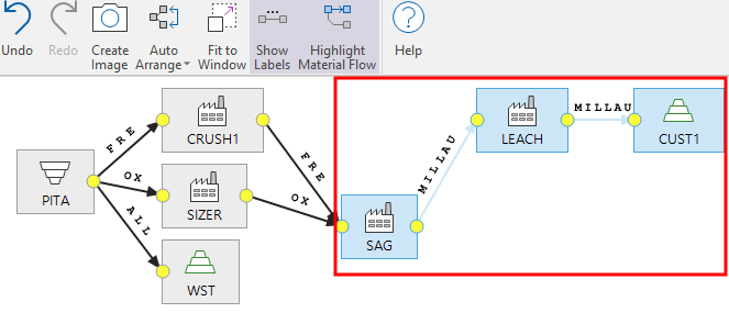
The material flow nodes associated with the chosen material bin(s) are highlighted in the graph:
|
|
|
View the online help for this function. |