Polygon
![]()
This function shares many of the same polygon modelling options as the other implicit modelling tools in the application. The biggest difference is in the way it defines the polygon: you use the Condition polygons option on the Input tab to adjust the distribution of vertices within each polygon. The two settings are:
- Minimum separation between points: Use this to exclude points that are too close together, which may cause the model to appear noisy or incorrect.
- Maximum separation between points: Use this to add points to the polygons so that there is an even distribution both along and between polygons.
Use Condition polygons to produce a similar number of vertices between sections and within the polygons.
Input
File
On the Input tab of the Polygon Modelling form, double-click (or click on the Select icon) to select a file containing the polygons. You can also click the Pick from Vizex button to collapse the form and interactively select a layer containing the file to be inserted and return to the form.
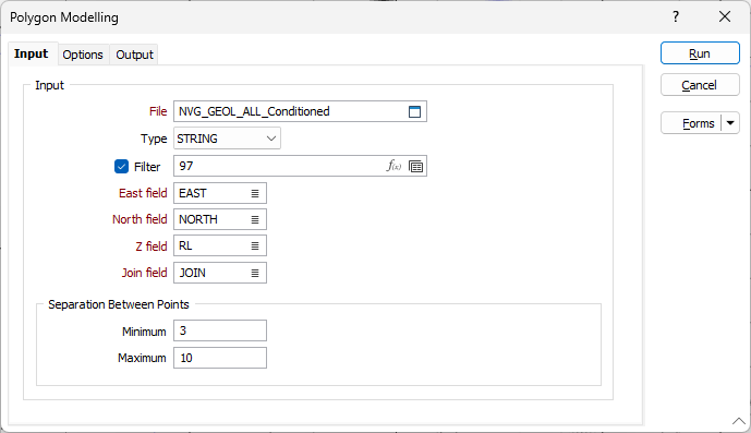
East, North and Z fields
Double-click to select the names of the coordinate fields in the Input file.
Join field
Specify the name of the field that contains the values that identify each string. If successive records have the same value in this field, then a line will join the points.
Orientation
Select the Orientation option if you want to specify the names of the fields for the orientation values.
The orientation of nodes on the string for which no Dip direction or Dip data is specified, or nodes inserted by the algorithm, will be interpolated from the orientation of the closest nodes in each direction.
Specify the Dip direction field for the input file using the list button.
Specify the Dip field for the file using the list button.
Specify the Polarity field for the file using the list button.
Note: Polarity identifies which side of the dipping plane the intrusion resides. A polarity value of +1 means the intrusion is above the dipping plane; while -1 indicates it is below the dipping plane.
If a Polarity field is not selected, or a value is not provided by the field, Polarity for the solid is taken to be +1.
Separation Between Points
Specify a 'Minimum separation between points' value to exclude points that are too close together, and which may cause the model to appear noisy or incorrect.
Specify a 'Maximum separation between points' value to add points to the polygons so that there is an even distribution both along and between polygons.
Forms
Click the Forms button to select and open a saved form set, or if a form set has been loaded, save the current form set.
Note: To better utilise processor resources across multiple applications and tasks, when running computer-intensive operations it may be necessary to reduce the number of cores used by the application.
To modify the number of cores the application can use:
-
Click the Project tab to open the backstage menu.
- Click on the Resources tab of the Options | System | System Options form.