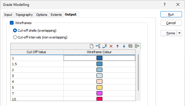
Output
On the Output tab of the form, specify the colour-coded lower cutoff values that will be applied to the result wireframes. The Name attribute of each wireframe will be appended with its cutoff value.
Wireframes
Cut-off Shells or Intervals
Select whether the output wireframe cut-offs should be Cut-off Shells (overlapping) or Cut-off Intervals (non-overlapping).
Selecting Cut-off Shells will produce 'nested' overlapping output wireframes. Selecting Cut-off Intervals will boolean the higher grade shells away from the lower grade shell so that the resulting wireframes do not overlap.
Cut Off Values and Wireframe Colours
Use the grid to determine how many Result Wireframes will be output as a result of the process and the Colours to apply to each. You can populate the list by selecting a Numeric colour set from the right-click menu.
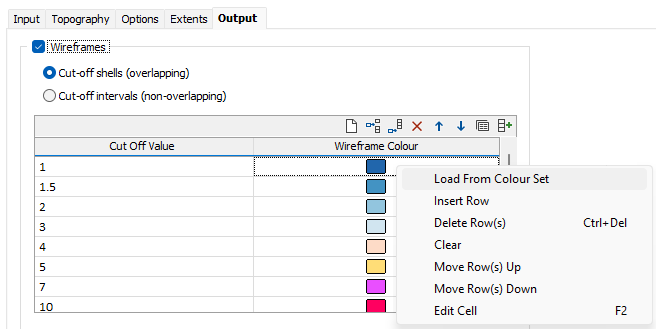
Each cutoff value represents a lower cutoff. Given a value of 0.7, for example, the resultant wireframe will enclose values of 0.7 and higher.
Use the buttons on the local toolbar to Manage the rows in the list.
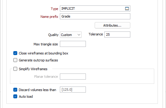
Type and Name Prefix
Double-click or click on the Select icon to set the Type and specify a Prefix for the wireframes that will be generated from the input data. The Cutoff value of each wireframe will be appended to the prefix to form a unique Name.
Code
Enter a Code that can be used to differentiate between the wireframes generated as a result of this process. If no Code Field has been assigned (or Code values are missing) from the input file, the Code value you enter here will be assigned instead.
Attributes
(Optional) Click the Attributes button and enter any other attributes for the output wireframes.
Tolerance
Specify a tolerance (in Grid units).
Quality
This setting provides a convenient way to control the quality and the speed of wireframe generation. There are five quality settings: Draft, Standard, High, Ultra and Custom.
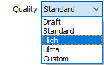
Setting the quality to Draft allows the general shape of the output wireframes to be generated quickly.
With the exception of Custom, each quality setting has a pre-set error tolerance value. The error tolerance for Draft is approximately twice that for Standard, which, in turn, is twice that for High, etc.
Setting the Quality to Custom allows a user-specified error tolerance. There is no limit to the user-specified error tolerance value (and hence the minimum mesh size), other than that imposed by available system memory.
Max triangle size
To eliminate large meshes, specify a Maximum Triangle Size parameter in grid units.
By default, mesh size is controlled by the tolerance parameter, which specifies the maximum error between the rendered surface and the actual surface. Typically, larger meshes are used where the surface is relatively flat, and smaller meshes are used where the surface has high curvature.
If a Max Triangle Size is specified then all triangles will be that size, or smaller if they fail the tolerance test.
Close wireframe at bounding box
If this option is selected, the wireframe will be closed automatically. If this option is not selected, the wireframe will be open where it intersects the specified extents and will not be
Generate outcrop surfaces
If Topography generation has been configured, you can select the Generate outcrop surface/s option to create outcrop surfaces for the output.
Simplify Wireframes
Select this option to reduce the number of vertices in the triangulation by eliminating those points that can be removed without causing the triangulation to move by more than the specified tolerance values:
- Planar Tolerance. This is the maximum amount that the triangulation is allowed to move in any direction after vertices are removed.
If no planar tolerance is specified, a default value of 0.01 will be applied automatically. Specifying a large planar tolerance will significantly alter the nature of the triangulation.
Discard volumes less than
If this option is selected, all independent triangle shells with a volume less than the specified minimum volume will be removed.
Any value less than or equal to zero will disable volume removal.
Auto load
Select this option to load the generated output in Vizex. The default draw style for an auto-loaded wireframe is 3D Shaded.
Implicit Model
Enter (or click on the ellipsis button to select) the name of an Output file.
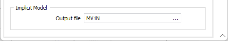
An Implicit Model (*.im) file can be used as an input to the Output Implicit Model functions on the Implicit tab, in the Tools group. This allows you to generate different output triangulations or points for the same model, without having to recompute the model each time.
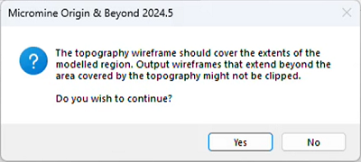
If the topograpy does not entirely cover the area covered by the bounding box, a warning prompt will appear.