Slices of Tubes Extruded from Reference Grid
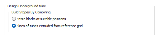
The following design parameters apply when the Build Stopes by Combining -> Slices of tubes extruded from reference grid option is selected on the Design | Underground tab of the Underground Mine Setup form.
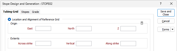
This form accepts the parameters for the tubing grid in which the stoping tubes will be extruded into the block model, and the design criteria for the stopes.
Tubing Grid
Select the Tubing Grid tab to specify the parameters for the tubing grid in which the stoping tubes will be extruded into the block model.
Location and Alignment of Reference Grid
Select the Location and Alignment of Reference Grid option to configure the Origin and Extents and Reference Axes details for the stope design tubing grid.
Origin
Specify the coordinates of the starting point (origin) for the axes of the tubing grid:
East
Specify the easting coordinate of the starting point for the axes of the tubing grid.
North
Specify the northing coordinate of the starting point for the axes of the tubing grid.
Z
Specify the elevation (Z) coordinate of the starting point for the axes of the tubing grid.
Extents
Enter parameters to define the dimensions (size) of the tubing grid in each direction.
Across strike
Specify the dimension (> 0.0) of the tubing grid across the widths of the extruded tubes.
This dimension is the width of the face plane from which the tubes will be extruded.
Vertical
Specify the dimension (> 0.0) of the tubing grid across the heights of the extruded tubes.
Along strike
Specify the length (>= 0.0) of the tubes to be extruded orthogonally away from the face plane of the tubing grid.
If this field is set to zero (0), or left blank, the tubes will be extruded to the far edge of the block model.
The sum of the lengths and separations of the generated stopes is limited by this value.
When clicked, the Auto Calc button will calculate the Origin and Extents of the tubing grid and insert them into the form.
![]()
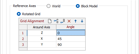
Reference Axes
Select the axes to which the definition of the orientation of the tubing grid is referenced.
World
Select this option to indicate that the orientation of the tubing grid is specified relative to the coordinate system for the mine.
Block Model
Select this option to indicate that the orientation of the tubing grid is specified relative to the block model.
This option may be useful when the block model is rotated relative to the coordinate system for the mine. When the block model is not rotated, selecting this option has the same effect as selecting the World option.
Rotated Grid
Select this option to indicate that the tubing grid has 3 orthogonal axes, which may be rotated.
Using a right-handed set of coordinate axes, the Y-axis should be aligned along the strike of the stopes ("along strike"). The X-axis will then be "across strike" and the Z-axis will be "vertical". The tubes will be extruded from the rotated XZ plane parallel to the Y-axis.
Grid Alignment
Specify the axis rotations that are required to produce the required orientation of the tubing grid.
These rotations must be specified in the order in which they are to be applied, with each rotation specified relative to the orientation of the axes following the completion of the preceding rotation. (This is identical to the methodology used for specifying rotations for search ellipsoids in resource estimation.)
The number in the first column specifies the order in which the rotations will be applied.
Specify the following settings for each rotation:
Around Axis
Select the axis around which the rotation is to be performed.
Select ‘X’, ‘Y’ or ‘Z’ to specify that the rotation is to be performed around the corresponding axis of the reference coordinate system.
Angle
Specify the angle (0 <= x < 360, degrees) through which the tubing grid is to be rotated around the axis.
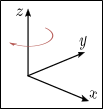
When looking from the end of the axis around which the rotation is to be performed, clockwise rotations are deemed to be positive.
Custom Grid - Plane
Select this option to indicate that the face plane, which is the plane from which the tubes will be extruded, of the tubing grid is to be aligned with a specified plane.
The across-strike and vertical axes of the tubing grid will be aligned with the axes of the specified plane.
Select the plane to which the tubing grid is to be aligned:
Reference
Select this option to choose the (XZ, YZ, XY) orientation of the tubing grid, relative to the coordinate system.
If the face plane of the tubing grid is to be aligned with a pre-defined plane, select the appropriate pre-defined plane:
XZ
(Default.) Select this option to align the face plane with the XZ-plane of the reference coordinate system.
YZ
Select this option to align the face plane with the YZ-plane of the reference coordinate system.
XY
Select this option to align the face plane with the XY-plane of the reference coordinate system.
Custom
Select this option to indicate that the face plane, which is the plane from which the tubes will be extruded, of the tubing grid is to be aligned with a plane with a specified dip and dip direction.
If d = Dip and D = Dip direction, the Y-axis on the plane will be set to the vector d→D and the vertical axis of the tubing grid will be aligned with this.
The across-strike axis of the tubing grid will be aligned with the X-axis on the plane, which will be the vector 00→D+090.
Custom > Dip
Specify the angle (-90 <= x <= 90, degrees, positive downwards) at which the plane dips, relative to the XY-plane of the reference coordinate system.
Custom > Dip direction
Specify the bearing (0 <= x < 360, degrees, clockwise from Y-axis of reference coordinate system) to which grid dips.
Example: If a plane dips 45° to the east, it can be specified as 45à090. The Y-axis is aligned with 45à090, the X-axis is 00à180 (which remains on the horizontal plane), and the Z-axis (which is also the normal to the plane) is 45à090. To specify this plane, set Dip = 45 and Dip direction = 90.
Stope Axis Orientations
If the stope axes on the specified plane are oriented with respect to the (rotated) axes of the tubing grid, specify the angles at which the respective axes are oriented, relative to the X-axis of the tubing grid.
Stope Axis Orientations > Across strike
Specify the on-plane angle between the across-strike vector of the stopes and the X-axis of the tubing grid.
This angle must be specified positive clockwise from the X-axis of the tubing grid.
The default value is 0 degrees, which specifies that the across-strike vector of the stopes aligns with the X axis of the tubing grid.
Stope Axis Orientations > Vertical
Specify the on-plane angle between the vertical vector of the stopes and the X-axis of the tubing grid.
This angle must be specified positive clockwise from the X-axis of the tubing grid.
The default value is 90 degrees, which specifies that the vertical vector of the stopes is perpendicular to the X axis, and aligned with the Y-axis, of the tubing grid.
Align Grid to Vizex View
Click the Align Grid to Vizex View button to change the orientation of the grid to face the current Vizex View. The grid rotation values in the form will be updated accordingly.
Edit Interactively
Click the Edit Interactively button to configure the design parameters for the stopes interactively in Vizex. The “Stope Design and Generation” form will be rolled up and a tubing grid will be displayed with respect to the target block model. See: Edit Interactively

Centreline Strings
Select the Centreline Strings option to configure the tubing grid details with a selected string file.
String file
Double click or in the String file field or click the folder button to select a string file to use for configuring the tubing grid. If required, you can select a Filter for the file.
East, North, Z
The East, North and Z fields from the string file may be automatically selected, or you can select the fields manually using the list buttons.
Join field
Select the Join field in string file from which join values for points in centreline strings are to be sourced.
Access path code
Optionally select the access path code field in the string file from which codes for haul roads or underground access drives (access paths) that are used to reach stopes are to be sourced.
Height offset
If required, enter a height value above the centreline strings at which the mid-point of the base of the tube is to be placed.
Reverse direction
Select the check box to set whether tubes are to be projected along segments commencing from opposite end of the centreline strings.
