Edit Interactively
Click the Edit Interactively button to configure the design parameters for the stopes interactively in Vizex. The “Stope Design and Generation” form will be rolled up and a tubing grid will be displayed with respect to the target block model.
The cross-sections of the stopes are predetermined by the spacing and the inclination of the lines defined by a grid (the "tubing grid"). The tubing grid may be oriented with respect to the target block model as required to ensure that the stopes are generated in the appropriate direction, which will be orthogonal to the plane of the tubing grid. This is referred to as the "strike" of the stopes (note that this may be different to the geological strike of the ore body.)
Grid lines will be shown on the grid (red) face to demonstrate how the stopes will be gridded.
An example stope will be shown that can demonstrate the minimum and maximum stope size, as well as its inclination. Solid lines show the minimum stope size; dashed lines show the maximum stope size. Ticks are shown along the example stope to indicate how it will be sliced.
The block model will be loaded into Vizex when interactive mode is started, and be removed when interactive mode is closed.
Interactively edit the grid
Double clicking on a face will align the view plane to be parallel to the face.
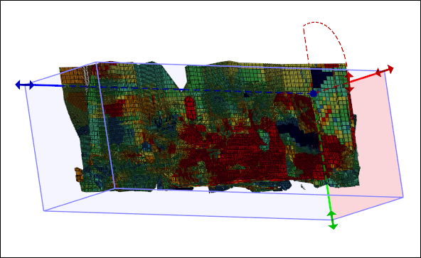
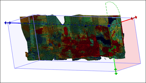
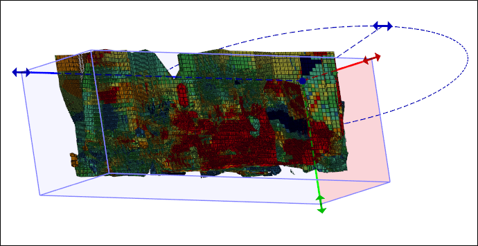
Handles at the corners of the grid rectangle can be dragged to manipulate the across-strike, vertical and along strike orientation of the tubing grid:
| Axis | Description |
|---|---|
| Across strike | Specify the width of the face plane from which the tubes will be extruded. |
| Axis | Description |
|---|---|
| Vertical | Specify the height of the face plane from which the tubes will be extruded. |
| Axis | Description |
|---|---|
| Along strike | Specify the length of the tubes to be extruded orthogonally away from the face plane of the tubing grid. |
Process the Changes
To process the changes that have been made interactively, press Esc or double-click the left mouse button on the header of the rolled-up form. The form will be redisplayed in its entirety and the values will be updated to reflect the changes. Click Save and Close to save the changes to the stope design, or Cancel to discard the changes and revert to the existing stope design.
The whole grid can be dragged by selecting it when a handle is not active.
Holding down X, Y or Z will restrict movement to that axis. Using the X, Y and Z keys while snapping, can be quite useful, especially for aligning the faces to objects.
Holding down the Shift key as you use the X, Y and Z keys will disable resizing along that axis. Pressing Shift + X, for example, will restrict resizing to the Y-Z plane, and disallow any change in the length of the X axis.
Collapsing the form by double-clicking the title bar, or via the Collapse option on the Forms drop-down menu, has the same effect as clicking the Edit Interactively button.
The grid rectangle uses the currently set Overlay colour and Selection colour settings (on the Selection tab of the Project Options | Vizex form).