Grid Limits
On the Grid Definition tab of the form, set the extents and the projection plane of the grid surface. The extents of the grid may be defined using either cell centres or cell edges; however, the created file will always be stored using the existing format (cell centres).
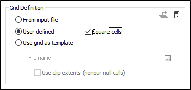
The limits of the grid surface can be defined in one of the following ways:
From input file
Double-click in the File name box or click on the Select icon to select the name of an Input file that defines the extents of the grid.
When this option is selected, the Square cells check box option is enabled. If the Square cells option is selected:
- the Y No. of cells option is disabled when the No. of cells option is selected in the Extents group
- the Y Cell size option is disabled when Cell size is selected in the Extents group
However, in both cases, their numerical values are always updated, and are controlled by the extents of the data and the user’s X-value selections.
Changing the Number of cells or the Cell size will adjust the grid limits based on the Input min/max data.
When XY values = centres, the Minimum X and Y match the Minimum X and Y of the Input file and are not adjusted further.
when XY values = edges, the Minimum and Maximum X and Y values are adjusted to be half of the cell size beyond the extents of the data.
User defined
With the User defined radio button selected, custom information can be manually entered in the Extents section.
Auto-fill from working plane
|
|
When a working plane is defined in Vizex, click the Auto-fill from working plane button to auto-fill the form with the Vizex plane definition. |

Auto Calculate from Input
Click the Auto calculate from input file icon to get the point file extents and the best fit plane and enter those parameters into the form.
![]()
This may be necessary when you need to reset the extents after previewing user-defined settings. You can then edit those parameters in the form.
Note that this option is unavailable when the Use grid as template option is selected.
User defined
When this option is selected, the Square cells check box option is enabled. If the Square cells option is selected:
- the Y No. of cells option is disabled when the No. of cells option is selected in the Extents group
- the Y Cell size option is disabled when Cell size is selected in the Extents group
However, in both cases, their numerical values are always updated, and are controlled by the extents of the data and the user’s X-value selections.
In the Extents group, all input options and selection options are enabled.
The Minimum and Maximum X and Y values will be adjusted if there is a change in the Number of cells or the Cell size. Double clicking in the Minimum cells gets the Minimum values of the Input file and recalculates the Number of cells, the Cell size, and the Maximum values.
Double clicking in the Maximum cells will recalculate the Number of cells and the Cell size and may recalculate the Maximum values if necessary (due to rounding up the Number of cells) to make the grid valid.
Use grid as template
When this option is selected, the Square cells check box option is cleared. The output grid will match the cell size and extents of the template.
Double-click in the File box or click on the Select icon to select the name of the Micromine Grid file to use as a template.
The File name is a mandatory input and the Use clipped extents (honour null cells) check box option is optional. If the Use clipped extents check box is selected any null cells in the template become nulls in the new grid. If this option is unselected the Output grid takes the full rectangular extent of the template grid.
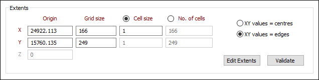
Extents
In the Extents group, the XY values = are enabled. Changing the XY values = selection updates the numerical Minimum and Maximum values on the form but does not alter the Output grid. All other options in the Extents group are disabled; however their numerical values are always kept updated.
If the User defined or the Use grid as template option is chosen, then selecting a new Input file (or changing the filter) will have no effect on the extents. If you want the extents to be based on a new Input file, select the From input file option.
Projection Plane
In the Projection Plane group, do one of the following:
- Select an Orthogonal plane definition
- Specify the parameters of a Transform plane definition
- Select an option to use the input point file extents to Auto calculate a plane of best fit
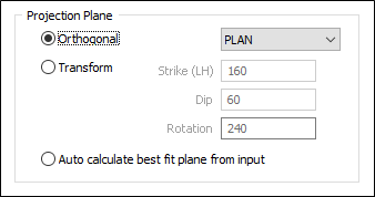
Orthogonal
Select the Orthogonal option to define an Orthogonal (LOOKING WEST, LOOKING NORTH, PLAN) projection plane.
Transform
Select the Transform option to define a transform projection plane.
Enter the Strike (LH), Dip, and Rotation values that will be used to calculate the transformation. The Dip value entered must be a positive number.
Strike and dip notation is inconsistent and must include the handedness of the measurement to make it unambiguous. In this case, the handeness of the strike is assumed to be left-handed. A left-handed strike is one where the structure slopes downwards to the left when viewed along the direction of strike.
You can also click the Edit Extents button to interactively define the projection plane: See: Workflow for Setting Interactive Grid Extents
Auto calculate best fit plane from input
Select this option to use the extents of the input point file to calculate a plane of best fit.
Extents
XY values =
The XY values = options are always enabled and can be switched at any time. Doing so alters the values shown in the Extents but does not alter the Output grid in any way.
Origin and Grid Size
If XY values = centres is selected, the Origin X and Y values display the centroid coordinates of the origin (minimum X, Y) and end (maximum X, Y) cells. Thus the grid will extend one-half of a cell size in all directions beyond the displayed coordinates.
If XY values = edges is selected, the Minimum and Maximum X and Y values display the outer edge coordinates of the origin and end cells. Thus the grid extents will exactly match the displayed coordinates.
Z Origin
This input is enabled when a non-plan orientation has been selected. If the projection plane of the grid is an orthogonal PLAN view, the origin is set to zero and the input box is disabled.
Cell size
In From input file mode, if Cell size is selected, the entire No. of cells row becomes disabled, although its values are still kept updated. The X and Y Origin, and optionally the Z origin, are calculated so that the outer edges of the origin cell extend at least 0.5 x cell size beyond the input data and correspond to a multiple of 0.5 x cell size. The X and Y Grid Size and No. of cells are then calculated so that outer edges of the end cell also extend at least 0.5 x cell size beyond the input data. (In other words the grid will always extend somewhere between 0.5 x and 1.0 x cell size in all directions beyond the input data.)
This takes place automatically in From input file mode; in User defined mode it must be triggered manually by double-clicking the minima and maxima.
No. of cells
In From input file mode, if No. of cells is selected, the entire Cell size row becomes disabled (values are kept updated). The X and Y Cell size and temporary number of X and Y cells are calculated to match the exact extents of the input data. One additional cell is then added to the temporary numbers of cells and the entire grid definition is then shifted 0.5 x cell size to the southwest. Thus the grid will always extend 0.5 x cell size in all directions beyond the input data.
This takes place automatically in From input file mode; in User defined mode it must be triggered manually by double-clicking the minima and maxima.
Edit Extents
When the grid definition is user defined, click the Edit Extents button to collapse the form and visually adjust the extents of the grid. Interactively adjusting the extents rectangle in Vizex, or in the Vizex Property Window, will update the values in the form.
Validate
If the grid definition is User-defined, or you have interactively edited the extents of the grid, an option to validate the extents is available. When you click the Validate button, the X and Y grid sizes are updated to make the grid correct, if necessary.