Stope Optimiser
![]()
The Stope Optimisation and Pit Optimisation modules enable you to determine the most profitable stope layouts, or sequence of nested stope layouts, for a block model using the integrated mathematical programming solver in conjunction with discounted cash-flow analysis. It's features include:
- Built-in material flow model with support for material bins defined by simple filters or complex expressions.
-
For Stope Optimisation: Build stopes by combining either (i) entire blocks at suitable positions, or (ii) slices of tubes extruded from a reference grid.
- Optimisation based on pre-assigned block values or those derived from built-in material flow model.
- Support for sub-blocked models.
- Inclusion/exclusion of zones defined by polygons/wireframes.
- Support for multiple regions with different pit or stope parameters – including sizes, orientations and planes, DTMs or centreline strings to which they should be bound.
- Processes multiple elements from multiple rock types with multiple processing methods.
- Support for dilution and recovery.
- Accepts element prices and mining, processing, rehabilitation, sales, general and administration costs, capital expenditure and discount rates.
- Produces pit or stope wireframes and/or coordinates of blocks comprising an optimum solution.
- A detailed suite of reports that can be customised, summarised and have unit conversions applied using new Report Generator.
- Scenario analysis using charts.
Except for the design parameters, which are different for stopes and pits, the user experience for the Stope Optimiser is very similar to that for the Pit Optimiser – if you can use one, you can use both.
Option 1 — Stopes from Combinations of Entire Blocks at Optimal Positions
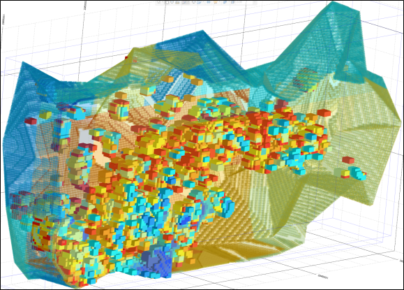
As with pit optimisation tools that utilise the Lerchs-Grossmann 3D Graph Theory or Pseudoflow algorithms, the entire-block stope optimiser, which was first released in 2020, requires a three-dimensional fixed block model of the deposit in which each block has been assigned a value that represents the expected economic return from the block after the material contained within it has been extracted, processed and sold.
Like the pit optimisers, the stope optimiser determines the optimum combinations of entire blocks that should be mined in order to maximise the total value of the extracted blocks subject to the satisfaction of the design requirements. Whereas the design requirement for the pit optimisers is that the specified minimum slope angles must not be exceeded, the design requirement for this stope optimisation approach is that each extracted block must form part of a stope of the minimum size and shape.
In each case, the final optimum shapes and sizes are formed from combinations of entire blocks. Neither optimiser can process sub-blocked models directly because the algorithms rely on all blocks being the same size. Where sub-blocked models are provided, the models are “regularised” automatically to the size of the parent blocks prior to the optimisation.
This approach works to the resolution of the parent blocks in the block model to determine the optimum locations for stopes of the specified minimum size and shape. It also provides a variety of options, including exclusion zones, control strings and elevations, to control where those stopes are positioned.
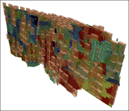
Option 2 — Stopes from Combinations of Slices of Tubes Extruded from Reference Grid
When considered in cross-section relative to the direction of stoping, some stoping methods require the stopes to generated within the constraints of a regular grid pattern. The new “tubes and slices” method implemented in version 2021.5 supports this by approaching the problem from a different perspective.
Whereas Option 1 determines the optimum locations for stopes of the specified minimum size and shape, this alternative approach allows you to specify the cross-sectional design requirements relative to a two-dimensional grid pattern, along with the position and orientation of that grid relative to the target ore body. It then projects “tubes” from the cells of the grid into the ore body and cuts these tubes into thin slices, for which the economic values are determined.
The quantities and starting locations for the tubes are defined by the grid (the "tubing grid"). The tubing grid may be oriented with respect to the target block model as required to ensure that the stopes are generated in the appropriate direction, which will be orthogonal to the plane of the tubing grid and is referred to as the "strike" of the stopes. (This may be different to the geological strike of the ore body.) The cross-sections of the stopes are predetermined by the spacing and inclination of the lines in the tubing grid.
Using the along-strike design minimum and maximum stope lengths, separation, and near and far dilution lengths, the mathematical programming solver recombines the slices to form stopes that satisfy the specified value or grade requirements optimally.
In contrast to Option 1, for which the stope granularity is dictated by the sizes of the blocks in the regularised model, the new tool works with wireframes, cutting and slicing blocks as required to follow the tube, boundaries of the ore body and any exclusion zones. As a result, the stope granularity is the thickness of a single slice, which you can specify, and the tool is well-suited to detailed design.
Information Requirements
To ease the transition from pit optimisation into stope optimisation, both stope optimisation options use the same economic evaluation engine and parameters as their pit optimisation counterpart. In addition, both use the same integrated mathematical programming solver – neither requires additional investment into a separate licence for the solver. Due to the differences in the approaches adopted by the two options, each offers pros and cons for different applications.
Option 1, which forms stopes from combinations of entire blocks, requires minimal prior knowledge of the profitable locations and orientation of the ore body or stoping method. This renders it highly suitable for greenfields projects and feasibility studies – the same types of projects for which preliminary pit optimisation work would be undertaken. It is also suitable for determining the outer economic limits of massive ore bodies.
In contrast, Option 2 requires more upfront knowledge of the structure of the ore body and the proposed stoping method, making it better suited to brownfields projects and detailed mine design. It is also likely to yield more useful results on tabular ore bodies than Option 1, for which the corresponding stope outlines are likely to be much coarser.
Although the objectives are ostensibly the same, there are fundamental differences between the methods employed by the alternative implementations. These differences are summarised in the table below:
|
Criterion |
Entire Blocks |
Tubes and Slices |
|---|---|---|
|
Optimisation Objective |
Best positions for stopes of the specified minimum size and shape. |
Best sizes and shapes for stopes placed at specified positions. |
|
Sub-Blocks |
Regularised to size of parent block with re-aggregation of values as required during post-processing. |
Supports all block sizes specified in block model. |
|
Stope Shape Modelling |
Combines adjacent entire blocks as required to form specified minimum size and shape of stope at positions. |
Extrudes tubes with specified cross-sectional shapes and sizes through block model and combines slices of those tubes as required to form stopes along the lengths of the tubes. |
|
Block Splitting |
Not supported. |
Supported. |
Applications
Using appropriate combinations of design parameters in conjunction with suitable economic parameters, the
- Identifying regions within a resource that can be mined profitably using sublevel open stoping, cut-and-fill stoping, shrinkage stoping, bighole stoping, vertical crater retreat, room-and-pillar mining, sublevel caving or block caving;
- Optimum sizing and staging of underground mining operations using standard pit optimisation methodology and discounted cash flow analysis;
- Determining the optimum outer envelope for profitable mining subject to a minimum mining volume;
- Planning locations of underground access drives; and
- Identifying ore and waste envelopes for use in ring design.
Material Flow Model
The user interface for the
Costs of mining, processing, stockpiling and sales can all be specified.
The
The material flow model used by the
- Single mine
- Single waste dump
- Multiple material bins
- Multiple elements from material bins
- Multiple processing facilities
- Multiple rock types
- Multiple stockpiles
- Multiple customers – with limit of 1 element for each customer
All material is sourced from the mine, which is represented by a block model.
Waste material is sent to the waste dump, which is created automatically to accept an unlimited quantity of any type of material. The properties of the waste dump cannot be changed.
Material extracted from the mine is classified using filters or expressions into material bins, which can be used to control processing and stockpiling.
The purpose of the mining operation is to produce one or more elements for sale to customers.
Elements are extracted from material bins at processing facilities.
Mining cost adjustment factors (MCAF) and rehabilitation costs can be specified for different rock types.
Material that cannot be processed immediately after extraction can be sent to stockpiles to be stored until it is processed later.
Customers purchase the elements extracted by processing facilities. Each customer can purchase an unlimited quantity of one element, and each element can be sold to one customer.