Alignment
Within the defined stope design region, stopes can be generated:
- at any location (“unconstrained”);
- on a digital terrain model (DTM);
- on a trend surface DTM that passes through a reference point;
- on a plane that passes through a reference point;
- on a DTM or plane repeated at regular vertical intervals from a reference point; or
- on centreline strings.
In each case, the position of a stope is deemed to be the location at which the origin point for its axes is placed. You can change how the stopes are positioned relative to the reference surface or string by setting the directions of the axis vectors appropriately. For example, if one of the axis vectors points downwards, the stopes will appear to “hang” from the reference surface.
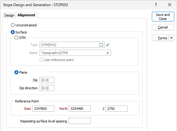
Unconstrained
Select if stopes may be generated at any feasible location within the stope design region.
Surface
Select if the origin of each generated stope must lie on a surface, such as a digital terrain model or a plane.
DTM
(Surface only.) Select if the origin of each generated stope must lie on the surface defined by a digital terrain model (DTM).
Type
(Surface only.) Select the type of digital terrain model upon which the origin of the generated stopes must lie.
Name
(Surface only.) Select the name of the digital terrain model of the specified type upon which the origin of the generated stopes must lie.
User reference point
(Surface only.) Select to use the DTM as a trend surface that passes through Reference Point.
Plane
Select if the origin of each generated stope must lie on the plane defined by a dip and dip direction that passes through Reference Point.
Usually, dip and dip direction parameters are used to specify the direction of a vector. However, by aligning the y vector (unit vector coordinates (0, 1, 0), or 00→000), from a horizontal plane that has not been rotated, into the direction of maximum dip of the plane and observing the dip and dip direction of that alignment, it is also possible to define the plane using these parameters - and this convention is used elsewhere in the application.
Dip
(Plane only.) Specify the angle (0 <= x <= 90, positive downwards) at which the plane dips, relative to the horizontal plane.
Dip Direction
(Plane only.) Specify the bearing (0 <= x < 360) to which the plane dips.
Example: If a plane dips 45o to the east, it can be specified as 45→090 – and the rotated y vector is 45→090, the rotated x vector is 00→180 (which remains on the horizontal plane), and the rotated z vector (which is also the normal to the plane) is ‑45→090. To specify this plane, set Dip = 45 and Dip direction = 90.
Reference Point
(Surface only.) Specify the reference point through which the surface, on which the origin of the generated stopes must lie, must pass.
East
(DTM | Use reference point, or Plane only.) Specify the easting coordinate of the reference point through which the surface must pass.
North
(DTM | Use reference point, or Plane only.) Specify the northing coordinate of the reference point through which the surface must pass.
Z
(DTM | Use reference point, or Plane only.) Specify the elevation (Z) coordinate of the reference point through which the surface must pass.
Repeating surface level spacing
(Surface only.) Specify the vertical distance between repetitions of the surface, in accordance with:
|
Level Spacing |
Effect |
|---|---|
|
> 0 |
Surface repeated within optimisation region at intervals of specified level spacing above reference surface. |
|
0 |
Surface not repeated. Origins of generated stopes restricted to reference surface. |
|
< 0 |
Surface repeated within optimisation region at intervals of specified level spacing below reference surface. |
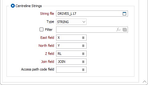
Centreline Strings
Select if the origin of each generated stope must lie on a string from a specified file.
String file
(Centreline Strings only.) Specify the name of the file that contains the strings upon which the origin of the generated stopes must lie.
Type
(Centreline Strings only.) Select the type (DATA / SURVEY / STRING / SECTION / ODBC LINK / MDB LINK) of file that contains the strings upon which the origin of the generated stopes must lie.
Filter
(Centreline Strings only.) Optional. Select to specify a filter to be applied to the String file to identify the points to be included in the strings. Specify the filter.
East field
(Centreline Strings only.) Select the field in the String file from which the easting coordinates for the points in the centreline strings are to be sourced.
North field
(Centreline Strings only.) Select the field in the String file from which the northing coordinates for the points in the centreline strings are to be sourced.
Z field
(Centreline Strings only.) Select the field in the String file from which the elevation (Z) coordinates for the points in the centreline strings are to be sourced.
Join field
(Centreline Strings only.) Select the field in the String file from which the join values for the points in the centreline strings are to be sourced.
Access path code field
(Centreline Strings only.) Optional. Select the field in the String file from which the codes for the haul roads or underground access drives (the “access paths”) that are used to reach the stopes are to be sourced.
This code is saved in the AccessPathCode attribute for each stope wireframe.