Entire Blocks at Suitable Positions
The following design parameters apply when the Build Stopes by Combining -> Entire Blocks at Suitable Positions option is selected on the Design | Underground tab of the Underground Mine Setup form.
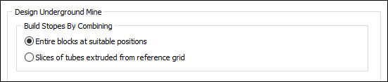
This form accepts the size and shape of the stopes to be formed from combinations of entire blocks, along with any restrictions on where the stopes can be placed within the optimisation region.
Design
Select the Design tab to specify the size, shape and stacking and pillaring requirements for the stopes.
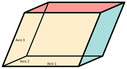
The nominal stope shape is a parallelepiped defined by 3 vectors that correspond to the axes of the stope, as illustrated below:
Stope Axes
Specify the following settings for each axis of the stope.
Note that the axes of the stope must not all lie in the same plane; however, there is no requirement for any of them to be perpendicular to each other.
It must be possible to model the required stope size, shape and separation adequately using combinations of adjacent blocks from the block model.
Rows may not be appended to or removed from the grid list.
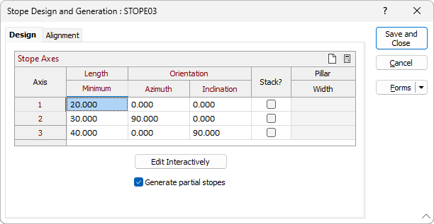
Minimum Length
Specify the minimum length of the axis.
Orientation
Azimuth
Specify the bearing (0 <= x < 360, positive clockwise from North) of the projection of the stope axis on the horizontal plane.
Inclination
Specify the angle (-90 <= x <= 90, positive upwards from horizontal) between the stope axis and the horizontal plane.
Stack
Select whether adjacent stopes should be co-facial wherever possible in the direction of the axis.
Pillar Width
Specify the minimum separation distance (>= 0) between adjacent stopes.
Edit Interactively
Click the Edit Interactively button to configure the design parameters for the stopes interactively in Vizex. The “Stope Design and Generation” form will be rolled up and an outline of the block model will be displayed with a representative stope shape positioned on the bottom-left corner. See: Edit Interactively
Generate partial stopes
Select whether partial stopes may be generated as appendages to existing entire stopes.
This option controls whether stopes are permitted to overlap.
Specifying 3D Rectangular Prisms with Optional Rotations
If the shape of the stope is a three-dimensional (3D) rectangular prism in which the axes are perpendicular to each other, the appropriate axis lengths and orientations can be calculated and inserted into the grid list by pressing the Auto Calc button at the top right of the grid list.
See: Stope Axis Auto Calculate
![]()
Clearing the Stope Design
Press the Clear button at the top right of the grid list to clear the stope design.
![]()
Alignment
Select the Alignment tab to specify the surfaces or centreline strings on which the stope axis origins must be aligned. See: Alignment