Add a Panorama Job
Panorama Jobs are created to generate extracted core photos from core tray photographs (tray to stick conversion). The options configured in the Panorama Job wizard will determine the source images and the settings for the output images.
Jobs are created from the Panorama Job Manager. To open the Job Manager you will need to be signed into Nexus - see Nexus for details.
With the Job Manager open,
-
Click the Add Job button at the top right of the Jobs panel.
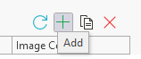
The Panorama Job form opens.
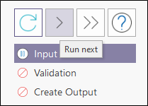
In the menu at the left, the Run Next and Run All arrow buttons can be used to process the current screen and step forward, or to process all screens to the final screen respectively.
The Re-run Current button will reprocess any job you have opened in the Panorama Job form.
If you click the Help icon, the Micromine Geobank online Help for the Panorama function will be opened in a browser window.
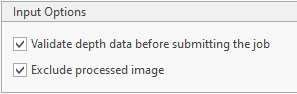
In the Input Options panel, if you select the Validate depth data... option, depth data for the input image/s will be validated before the job is submitted for processing.
If you select the Exclude Processed Image option, if inference has already been run on an image, then it is not sent to the job framework again and will not be included in this job. This option can be useful where a folder contains new images and only those are to be processed. If you select this option and add to the job a single file that has already been processed, an error message will be received.
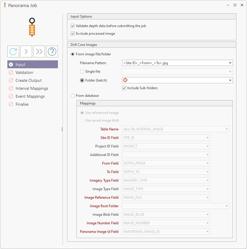
The Drill Core Images panel of the Panorama Job form provides input fields used to select the image/s for processing by the Job Manager. The Panorama Job process converts Core tray images into named photos of the extracted core using the depth and other data for the tray image.
Note: Panorama always extracts cores as left to right, top to bottom for horizontal core trays, and bottom to top, left to right for vertical core trays:
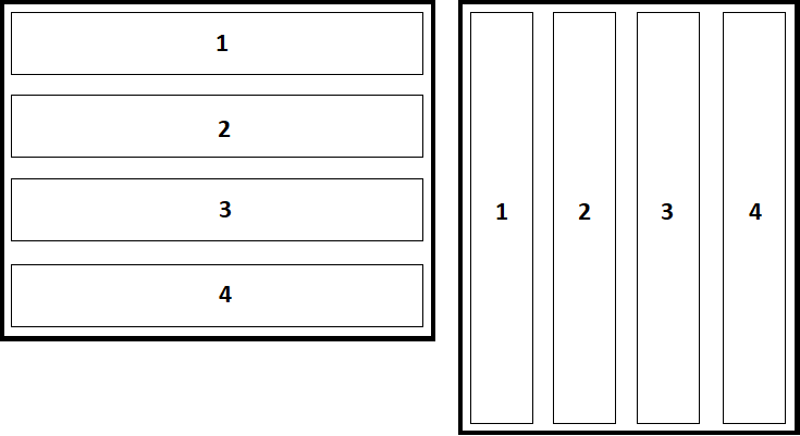
Any other orientations (such as if the image is flipped) will cause the core trays to be stitched in the wrong order during post-processing.
Output images are centre-aligned. This means that if a job contains a thick core and a thin core, for example, the output from the core extract process will centre-align the thin core to the thick one in the one image - making it easier to interpret the results.
The Panorama Job can be performed using a single file, a folder full of images, or referenced images or saved image blobs from the Database.
Panorama log files which can be used to debug any job framework issues, are located in C:\ProgramData\Micromine\Geobank\Logs\Panorama.
Single File
To process a single core tray image using the Panorama Job form,
-
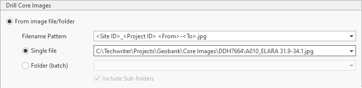
Select the From Image File/Folder option.
-
Select the Single File option.
-
Use the drop down provided to navigate to and select the Single File to be processed.
-
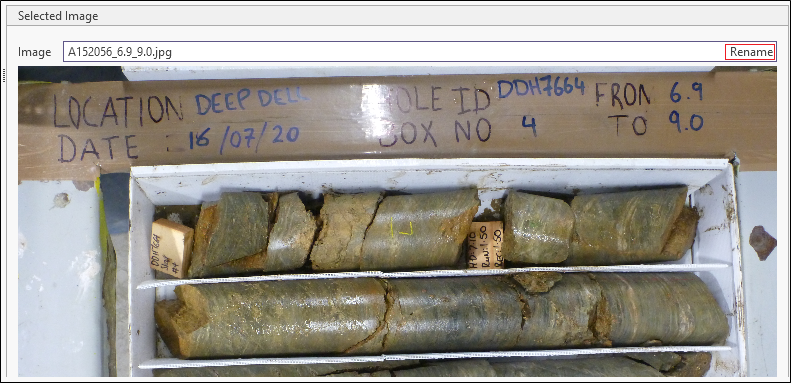
Use the Filename Pattern drop down to select the file name mask that matches the selected image file name.
For example, a basic filename pattern would be <Site ID>_<From>_<To>.jpg for .jpg files with Site ID and Depth information separated by underscores. If you select the pattern closest to the required mask, you can then modify the information as required. In the example below, the basic pattern has been modified to <Site ID>_<Project ID> <From>-<To>.jpg to match the name of the file.
The field names available to use inside angular brackets in the mask are:
-
Site ID (SITE)
-
Project ID (PROJECT)
-
From (DEPTH_FROM)
-
To (DEPTH_TO)
-
Image Type (IMAGE_TYPE - typically Wet/Dry)
Regular expressions that can be used within the mask are:
-
* (Wildcard)
-
\ (Escape)
Any other text will be matched as provided in the mask.
For information on other regular expression syntax, see regexr.com
Note: You cannot use a wildcard expression next to a tag unless there is another character after the wildcard, before the next tag to indicate the end of the wildcard. Any character can be used to signal the end of a wildcard, including a space.
When the relevant information has been configured,
-
Click the Run Next button in the panel at the left of the form.
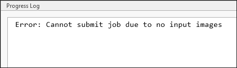
A prompt will display the progress of the addition of the selected image\s to the database.
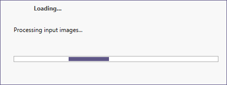
When processing of the input image/s is complete, the job will progress to the Validation stage.
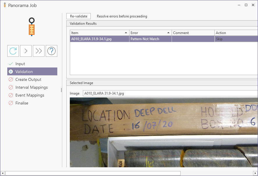
The Validation process checks whether or not the file matches the pattern.
As an example of the mask pattern not matching the image, for a .jpg image named with a dash between the From and To information, if you were to select the following standard mask in Input:
<Site ID>_<Project ID> <From>_<To>.jpga mismatch would occur because of the underscore (instead of a dash) in your mask - as shown below:
You will need to submit separate jobs for batches with incompatible patterns - i.e. one job has one pattern.
The Validation Results grid will display any validation errors that may have occurred. You can use this information to correct any errors. For example, you can Rename a file using the button provided to match the mask Filename pattern and successfully complete validation:
When any errors are corrected, you can revalidate the data using the Re-validate button.
If no errors are present, the message All depth data is valid will be displayed above the grid.
-
Click Run Next when the validation is complete.
This will progress the job to the Create Output stage.
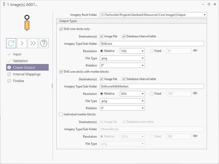
The Imagery Root Folder drop down must be used to select the root folder in which the output image/s will be stored.
The Output Types panel contains options to configure the settings for output files. Setting no output options results in only masks and other metadata stored as output.
Three options are available for the output types. which can be selected individually or in combination:
-
Drill Core Sticks Only - Select this option to create images showing only the drill core sticks.
-
Drill Core Sticks with Marker Blocks - Select this option to create images which show the drill core sticks and the labelled marker blocks.
-
Individual Marker Blocks - Select this option to create an individual image for each marker block from the tray.
For each output type, there are a number of configurable options:
-
Destination(s) - The Image File and Database Interval Table options determine the output destination/s for the resultant file/s. options can be selected individually or in combination and determine the output destination/s for the resultant file/s. If Image File is selected, images will be save to the file system in the specified output folder. If Database Interval Table is selected, the metadata and image/reference will be saved to the nominated database table. These options can be selected individually or in combination
Note: As with all incoming data, it is recommended to save to Buffer tables first for validation and later promotion.
-
Imagery Type / Sub-folder - Use the field provided to enter a name for the imagery type (typically Wet/Dry) or the sub-folder in which the output files are to be stored.
-
Resolution - The options for setting the resolution of the output image:
-
Relative - Resolution is calculated by length; for example, 50% means a 500 pixel wide stick becomes 250 pixels wide (total pixels is then a quarter of original).
-
Fixed - Select Fixed to enter a value in dpi for the image resolution
-
File Type - Select a file type for the image output from the list of available formats.
-
Rotation - Select an angle of rotation for the image output.
For cases where the input image is not displayed vertically, from the top of the core to the bottom, this value can be selected to ensure the core stick output is shown in the correct orientation.
-
When the required Output Types options have been configured,
-
Click Run Next to progress to the Interval Mappings for the job.
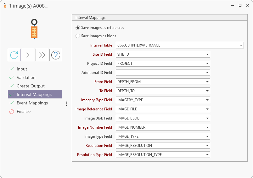
The Interval Mapping fields are auto-filled with default data. You can modify these selections as required. Mandatory Interval Mappings fields are indicated in red. One of the Save Image options must be selected:
-
Select the Save images as references option if you want to store the file path references to the images, rather than the images themselves, in the database.
-
Select the Save images as blobs option if you want the images to be stored as blobs (binary large objects) in the database.
With the required Save option selected, you can accept the Interval Mapping defaults, or
-
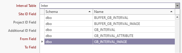
Select the required Interval Table for the mappings using the drop down look up list. You can enter text to filter the available tables.
-
Similarly, use the Site ID, Project ID and Additional ID fields to select the database table in which Site ID, Project ID and Additional ID are stored. Note: The Site ID field is mandatory. Project ID and Additional ID are optional selections.
The reason that Site precedes Project in this screen is because, in the context of drillholes in Panorama, Site is the main drillhole identifier and Project is simply an attribute of the drillhole which is part of the primary key. This means that the primary identifier ( Site ID) for the drillhole is Site, and the secondary identifier (Project ID) is Project. If your database has a tertiary identifier to determine uniqueness, Additional ID can also be mapped.
-
Select the database table containing the Depth From information using the From Field drop down.
-
Select the database table containing the Depth To information using the To Field drop down.
-
Use the Imagery Type drop down to select the field in which the type of imagery is stored - for example core tray, chips, downhole etc.
-
Use the Image Reference drop down to select the field in which the reference to the image file path is stored.
-
Use the Image Blob drop down to select the field in which the image blob is stored.
-
Use the Image Number drop down to select the field in which the image number data is stored.
-
Use the Image Type drop down to select the field in which image type data is stored - such as wet/dry for core trays.
-
Use the Resolution Field drop down to select the field in which the image resolution data is stored.
-
Use the Resolution Type Field drop down to select the field in which the image resolution type data is stored.
When the interval mappings have been configured as required,
-
Click Run Next to progress to the Event Mappings step.
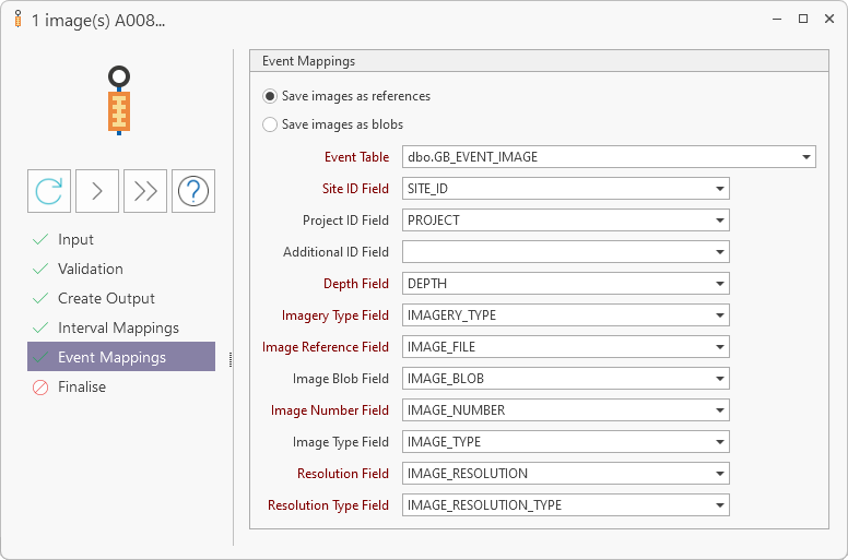
The fields in the Event Mappings panel are auto-filled with default data. You can modify these selections as required. Mandatory Event Mappings fields are indicated in red. One Save images option must be selected. This does not have to be the same option selected for the Interval Mappings.
The Event Mappings fields are similar to the Interval Mappings options, except the Event Table must be selected, and the From Field and To Field are replaced with a single Depth field. You can accept the default field settings, or modify them as with the Interval Mappings fields.
For details on setting the other Event Mappings options, see the above documented Interval Mappings information.
With the Event Mappings configured,
- Click Run Next to move to the Finalise step of the process.
- Click Run Next.
- You can close the message and click OK to return to the Job form.
(If Skip welcome message is enabled, clicking Run Next at the last step above will begin the process.)
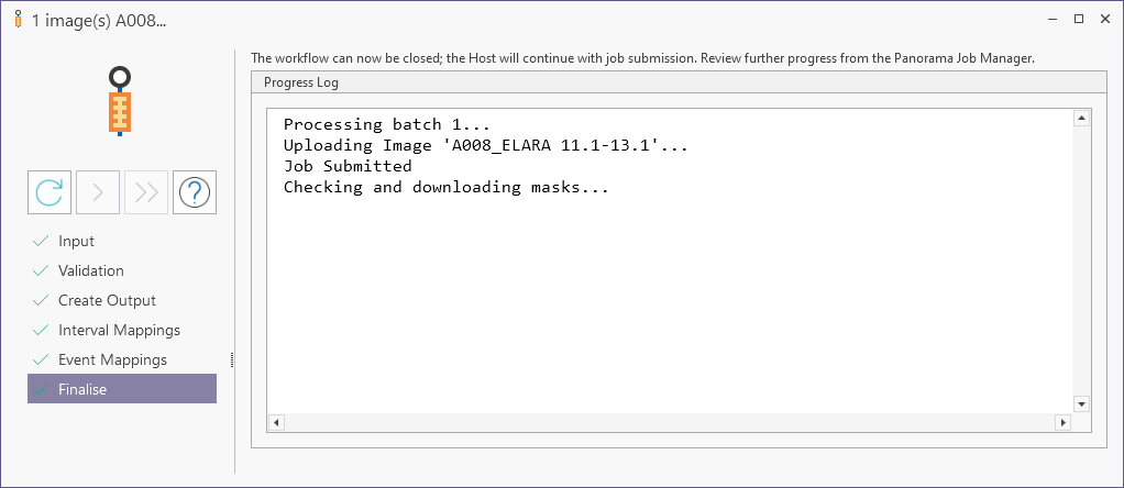
This will begin processing the job and you can now close the Panorama Job form.
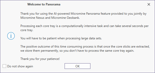
If Skip welcome message is not enabled in Panorama Options, an informational welcome prompt will be displayed.
As responses and output are received, the Job Manager will:
-
Update any status data which will then be displayed in the Progress Log and stored to the configured folder.
-
Store outputs (maps and metadata) to the Panorama repository
As described in the Finalise screen, information on the progress of the job can now be found in the Job Manager.
The output files configured in the Job Manager will be saved to the specified root folder in subfolders created by the application.
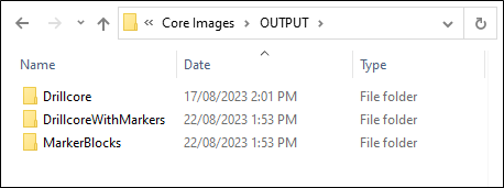
The drillcore images contained in the folders were created by the Job Manager to the specifications entered. Below is a cropped example of an image set to .png at a 10% relative resolution.

Folder (batch)
When processing a folder of images,
-
If you select the Exclude Processed Image Input option, any images within the folder/s or database that have already been processed will not be included in this job.
This means, for example, that if a folder containing multiple images is processed, the next job for that folder will only process any new images that have been added, and not those already processed. This workflow can be repeated daily or weekly as images are taken and added.
To configure the Folder (batch) process, in the Drill Core Images panel,
-
Select the From Image File/Folder option.
-
Select the Folder (batch) option.
-
Use the Folder (batch) drop down to select the folder for the job.
-
If you select the Include Sub-folders option, any sub-folders within the selected folder will also be processed as part of the job. Without this option selected, only files inside the root folder will be processed.

You can now follow the steps outlined in Single File to begin the batch Panorama Job process.
From Database
To process core tray image directly from a table in the database, in the Panorama Job form,
-
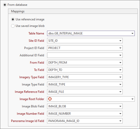
Select the From Database option.
-
Select one of the two available image options:
-
Select the Save images as reference option if the images to be processed are in the file system and the database contains the file path reference to the image.
-
Select the Save images as blobs option if the images to be processed are save as blobs in the database table.
-
Use the Table Name drop down to select the database table to be processed with the Panorama Job.
This is a mandatory field (as indicated in red) because it must contain the referenced image or image blobs required for the Panorama Job.
-
If you need to modify the default fields, map the remaining fields in the panel as required. Information on each field is contained in the table which follows:
The Mappings for the From Database option are auto-filled with the defaults. You can accept these settings, or modify them as required. The Table Name and Image Root Folder will need to be selected, regardless.
| Mapping | Description |
| Table Name | Mandatory. The database table in which the Referenced Images or Image Blobs for the Panorama Job are stored. |
| Site ID Field | Mandatory. The field in which Site ID is stored. |
| Project ID Field | The field in which Project is stored. |
| Additional ID Field | The field in which the Additional ID is stored. |
| From Field | The field in the database table containing the Depth From information for the job. |
| To Field | The field in the database table containing the Depth To information for the job. |
| Imagery Type Field | The field in which the type of imagery is stored - for example core tray, chips, downhole etc. |
| Image Type Field | The field in which image type data is stored - such as wet/dry for core trays. |
| Image Reference Field | The field in which the reference to the image file path is stored. |
| Image Root Folder | The root file system folder in which the output core extract images are to be stored. |
| Image Blob Field | The field in which the image blob is stored. |
| Image Number Field | The field in which the image number data is stored. |
| Panorama Image ID Field | The field in which the Panorama Image ID is stored. If this ID is present, the image will be marked as 'processed' and will not be processed again if the Exclude Processed Images option is enabled. |
When the Mappings options have been configured,
-
Click Run Next to proceed to the Validation step.
You can now follow the steps outlined in Single File to begin the Panorama Job process from the database.
For information on cloning or deleting the jobs you create, see Job Manager.