Plan View Configuration
Use the Configuration page of the Plan View Property Editor, to configure a plan view that can be used to display point, line, and boundary data in a spatial window.
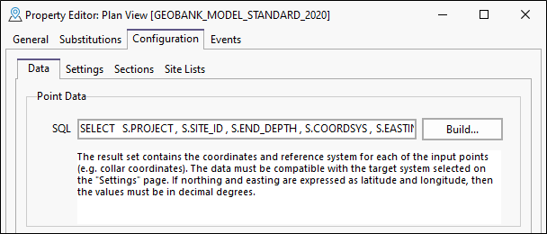
Point Data
Click on the Build button to load or create the SQL query that will retrieve the relevant point data. This SQL script retrieves data for the individual points displayed in plan view. The result set contains the coordinates and reference system for each of the input points (e.g. collar coordinates). The data must be compatible with the target system selected on the Settings page.
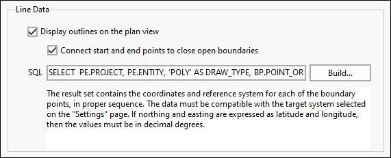
Line Data
If you want to display outlines on the plan view, select this check box.
Click on the Build button to load or create the SQL query that will retrieve the relevant line and boundary data. The result set contains the coordinates and reference system for each of the boundary points, in proper sequence. The data must be compatible with the target system selected on the Settings page.
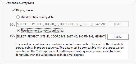
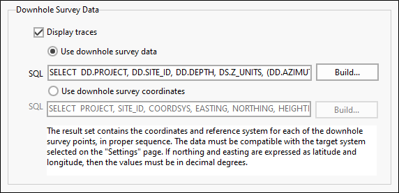
Downhole Survey Data
Use the Downhole Survey Data group to configure the display of projected downhole survey coordinates.
Display traces
This option is disabled by default. To load downhole survey data into the plan view, select this option.
Use downhole survey data
Select this option to project drillhole traces onto the plan view using downhole survey data.
Click the Build button to load or create the SQL query. The inclination and direction data that is obtained from the query is used to automatically calculate EASTING, NORTHING and HEIGHT coordinates expressed in the target coordinate system (specified on the Settings tab of the of the Plan View Property Editor).
The reference coordinate system is obtained from the query used to obtain the point data. Converted Easting and Northing downhole coordinates are then used to display the trace in Plan view by joining the points for each drillhole.
See: Downhole Survey Data
Use downhole survey coordinates
Select this option to project drillhole traces onto the plan view using downhole survey coordinates.
Click the Build button to load or create the SQL query. The downhole survey coordinates are transformed to the target coordinate system as specified on the Settings tab of the Plan View Property Editor. Easting and Northing downhole coordinates are used to display the trace in Plan view by joining the points for each drillhole.