Modelling Parameters
On the Modelling Parameters page of the IDW Estimation form, select an estimation model method, specify one or more input Grade fields, and specify the coordinate division fields for discretisation.
Model
Method
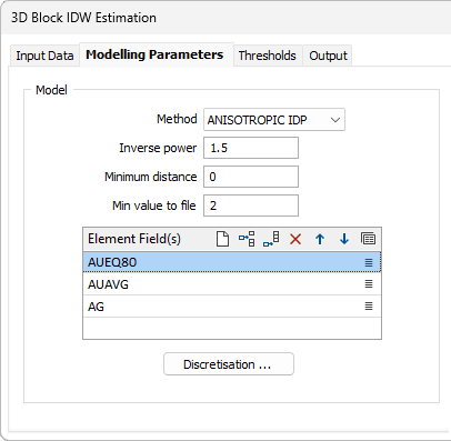
Choose either ANISOTROPIC IDP (the default) or INVDISTPOW as the estimation method. See: The different estimation (gridding) methods for 2D block
Inverse power
The weighting given to each point that falls within the search ellipse is inversely proportional to its distance from the block centre, raised to the value you enter in the Inverse power prompt.
Minimum distance
Enter the minimum distance between any sample point and the centre of the block being modelled. If true distance is less, the minimum distance value will be used instead. If the minimum distance is 8 metres, for example:
- the true distance between sample point C and the centre of the block is replaced with the minimum distance 8.
- the true distances between sample points A and B and the centre of the block are accepted.
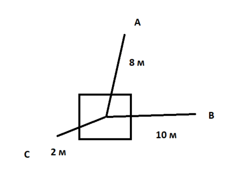
If we use a factor of 2 for example:
A = 1/8^2, B=1/10^2 and C= 1/8^2
the centre of the larger resized block will be interpolated, and nested blocks will also take this value.
This method can eliminate the overpowering effect of samples very near the block centre, but should not be used if the interpolation needs to honour the original data.
Min value to file
The minimum value that will be stored in the block model during an interpolation run. If an interpolation can be made, but does not reach this threshold, the block will be left blank.
Element fields
Additional attribute fields may be specified for multi-element interpolation. Typically, these will be elements which correlate closely within the domain being interpolated. Use the buttons on the local toolbar to Manage the rows in the list.
Discretisation
Click on the Discretisation button to specify the number of divisions in the East, North, and Z directions. These are integer values that control the number of discrete points to be estimated in each direction within each block (or sub-block). The values of all the discretised points are then averaged to estimate the value for the block, and the result of each block is written to the output file.
For example, if you choose 4 East divisions, 4 North divisions, and 4 Z divisions, the application will interpolate and average a total of 64 estimates within each block. Although the estimates for a given block all share the same input data, the distance from each input sample (and thus the weight) will be slightly different for each discretised point, producing a different result for each one. The result is a more accurate estimate, but at the cost of more computing time. See: Discretisation
Search
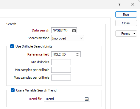
Double-click to load a Data Search form set. Alternatively, right-click in the input box to open a form where you can define the shape and direction of the search ellipsoid. See: Search Definition
Search method
Use the Search method drop down to select the required search method for the data search - Legacy or Improved.
With the addition of new fields in Micromine Origin & Beyond v25.0, a new and improved data search algorithm was created. The order of the named sectors for Octant and Quadrant search ellipsoids has also been modified to a Z-order in the improved Search algorithm, making it easier to know which sectors are opposite.
The new algorithm aims to minimise the average distance from the ellipse centre, while maximising the number of included points (subject to the constraints). If the new fields are not used, the old algorithm is used so that users do not get unexpected or different results. The Improved option will utilise the new algorithm, which is more flexible than the Legacy one, so even with the same parameters, it can find more and/or slightly different point sets.
Use Drillhole Search Limits
Select the option to enable the options for the sector search parameters.
Reference field
Select a field from the sample or composite file (i.e. Hole_ID) which will be used as a reference counter.
Min drillholes
Optionally, use the Min drillholes field to specify a minimum number of drillholes to be included in the search.
Min & Max samples per drillhole
In effect, the Min samples per drillhole and Max samples per drillhole values allow you to apply a filter condition. For example, you may want to ensure that, for every hole, you only count a certain number of "best" points.
- Min samples per drillhole is useful when you want to specify that you only want holes that have a certain minimum representation in a search neighbourhood (so that points are not counted, for example, when a hole has only one point in its search neighbourhood).
- Max samples per drillhole is useful when you want to specify that all the points found in a search neighbourhood should not come from a single hole.
Both parameters use the Reference field to constrain the drillholes that are selected by the interpolation process.
FOR EXAMPLE:
If Min samples per drillhole = 2, Max samples per drillhole = 6, Maximum samples per drillhole = 8, and the Reference field = HOLE_ID, then, for each search neighbourhood we want to find drillholes to base our calculations on:
The process will look at that search neighbourhood and only count from holes where at least 2 samples are present, only take the 6 "best samples", and take a total of 8 samples per sector (those 8 can be from any holes).
Note that if the Maximum samples per sector is left blank, the maximum value will default to 150. If you want to allow for more samples, you need to explicitly enter a larger upper limit. The higher the upper limit, the slower the process will be.
Use a Variable Search Trend
Select this option to use a structural interpretation of the raw data to model the semi variogram.
Double-click (or click on the Select icon) to select a (*.mmstf) Trend file. The structural trend file you select here is an output of the Create Trend function on the Block Model tab, in the Variable Trend group.
If this option is selected, your attribute fields (above) will need to reference an omni-directional variogram created using the same trend model.
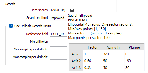
If you hover on a populated Data Search field, a pop up will display information on the parameters set for the selected search:
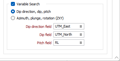
Variable Search
Select the Variable Search check box option to specify fields that contain variable values defining the rotation angles for the search ellipsoid, for each block in the file.
Where there is a significant directional variation in the continuity of the modelled mineralisation (in a folded structure for example) the Variable search option allows the rotation angles for the search ellipsoid to be defined. The search ellipsoid orientation can be controlled on a block-by-block basis, reflecting the directional trends in the mineralisation.
If you select the Dip Direction, Dip, Pitch option, you can select the fields containing these values for the variable search.
If you select the Azimuth, Plung, Rotation (ZXY) option, the Azimuth, Plunge and Rotation fields (for ZXY) can be specified.
These fields change the orientation of the variogram model as well as the search ellipsoid. Another way to think of it is that the variogram model axes are always aligned with the search ellipsoid axes.
If they are specified, the process will use the values in these fields rather than those defined in the Ellipsoid Parameters tab of the Data Search form.
If variable values in the block model file are missing, then the values defined in the Ellipsoid Properties tab will be used instead.
The Variable Search option can improve interpolation results for gently folded ore bodies. For data preparation prior to interpolation, the Flattening and Unfolding tools available in the application provide a more complex (yet more accurate) alternative.