Measure Tool
![]()
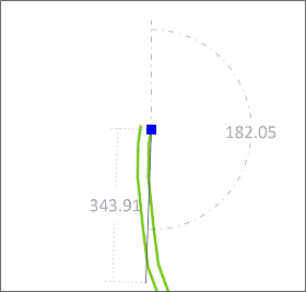
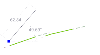
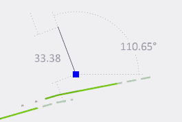
An annotation overlay is shown which includes the distance measured and the angle of the line. Which angle is shown will depend upon the orientation of the current view.
-
In Plan View (or rotated Plan View), an Azimuth angle (0 to 360°) is now shown with a DASHED reference line and a North arrow.
-
In Section View, an Inclination angle, +90° (up) to -90° (down), is shown with a DASHED reference line.
-
In an Oblique view, the Screen Plane angle relative to horizontal (0 to 180°) is shown with a DOTTED reference line.
Absolute or Relative Distance
You can enter absolute coordinates (the default) or select an option to enter coordinates relative to the previous point.
To measure the distance between points:
-
Click the Measure Tool in the Pointer Mode group:

The length, azimuth, inclination and gradient % of the line measurement is shown on the status bar as a reference.
As you measure, the length and angle of the line are shown as an annotation.
-
Shortcut Input mode , (comma) Cartesian coordinates 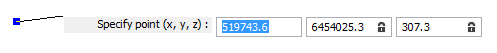
< Polar coordinates 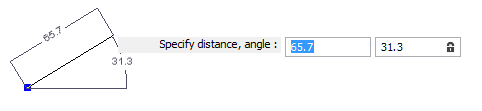
@ Switch to Relative mode to enter coordinates relative to the previous point. # Switch to Absolute mode to enter absolute coordinates. -
Click on the point where you want to start the measurement and any additional points to be included.
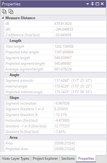
The calculated distance is updated in the information window. Information displayed includes the Total length, Projected total length (in the plane of the screen), Segment azimuth, Segment inclination (first/last), Gradient (1 in x), Segment length, Segment gradient, and the Projected segment length.
Delta X, Delta Y, and where appropriate, Internal angle, Projected Internal angle, and Z difference are also reported.
-
Double-click on the point where you want to finish the measurement.
The current segment 'rubber bands' to the current mouse location. This ensures that the reported values are always up to date. Each mouse click adds a new segment length to the totals, and replaces the previous segment gradient, length, azimuth and inclination, with those of the new segment.
If a polygon is measured, the area will also be reported. For polygons that are not closed, the tool assumes that the first and last points are joined.
To measure and restrict the new point to the direction of the last segment, hold down the CTRL key as you digitise the point with the mouse.
To measure and restrict the new point to be perpendicular to the last segment, hold down the SHIFT key as you digitise the point with the mouse.
To measure and restrict the point to the screen axis, hold down the x, y, z, u, or v letter key as you digitise the point with the mouse.
- Click on the Measure tool again to remove the measurement line and hide the information window.
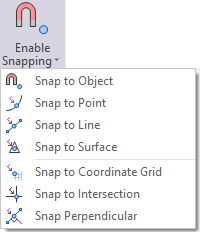
Snap mode
Optionally, select an option from the Snap Mode drop-down menu on the Home tab, or the Vizex tab, in the Snapping group, to enable a Snapping while you are measuring.
It is possible to perform a follow string by using the "snap to point" or "snap to line" modes and then left clicking and dragging along the line to follow.