Create Mining Blocks
The Mine Planner (on the Scheduling | Schedule tab, in the Optimise group) requires “tasks” or mining blocks to be based on a regular planar cutting profile. The cells in this profile all have the same dimensions and form a grid of rows and columns – much like a map referencing system.
The Create Mining Blocks tool on the Mining tab, in the Task Preparation group (and the Wireframe tab, in the Operations group), take a pit solid and generate mining blocks based on a planar, regular, cutting grid and equally-spaced bench heights. This provides output in the format expected by the Life of Mine (LOM) Planner.
The outputs are a wireframe containing the mining blocks and (optionally) a string file representing the cutting grid. Rather than a single pit solid, the input can be made up of multiple pit shell solids, each representing a separate phase, or stage, in the mining process.
In order to explain the Mine Planner workflow, the following example will use a single pit solid.
Select the pit solid wireframe on the input tab. There is an option to discard mining blocks with a volume less than a user defined value, and an option to merge blocks when the volume is less than a user defined value. If the block volume is less than the discard value it is ignored. If the block volume is greater than the discard value and less than the merge value, the block will be combined with the largest, mining block on the same bench and a common boundary. If there is no adjacent block, the original block will remain (unmerged).
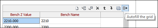
The Benches tab relates to the vertical definition of the pit. The Z value of each bench is defined in a grid list. The radio buttons at the top of the tab determine if these Z values represent the crest, toe or midpoint of the bench. The Bench Name is used to construct the name of each mining block wireframe. It will usually be a whole number, incrementing by the bench height. Both the Z value and/or the name can be written as (“Bench Z” and “Bench Name”) attributes to the wireframes.
There is no need to manually type in this information. The rightmost icon on the grid list toolbar will pop up a dialog with parameters to automatically generate all the bench values and names. The start value and the number of benches have a calculate option that will populate the response field based on the pit wireframe.

The Output tab of the Create Mining Blocks form defines the names of the mining blocks and where the wireframes will be written. It also populates attributes of the mining blocks and optionally creates Wireframe Sets to make it easier to display the mining blocks in Vizex.
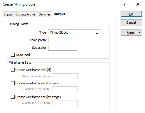
In the Mining Blocks group box:
- Define the wireframe type that will contain the output wireframes (right click to create a new type).
- Define the prefix and separator used in the generating the names of each mining block wireframe.
The name is made by concatenating the following components and the defined separator: Prefix, (Stage), Bench Name, Row, and Column.
In the Attributes group box, populate attributes of the mining block wireframes using any of the following: Block Index, Bench (Z), Bench (Name), Row and Column. If the Input uses Stages then the additional attributes Stage and Stage + Bench Name.
The Stage name used is defined in the Output column (on the Input tab).

If the mining blocks are to be used in the Mine Planner it is essential that the Block Index attribute is transferred to the output wireframe. The block index is a unique value that will be used to generate horizontal and vertical dependencies in the Mine Planner. The subsequent workflow also expects the Bench Name to be written to the output wireframes. In the scheduler this will be used to group tasks.
Note: If stages are used then the Stage + Bench Name should be written to mining block wireframes. In the Scheduler, this will be used to group tasks.