Wireframe Definition
Use the Wireframe Definition page to navigate to the section control file that will be used by the process and set the attributes of the output wireframes.
Section Control File
On the Wireframe Definition tab, click the ellipsis button (or double-click) to navigate to the location of the control file that contains the sections that will be mapped to the polygons in the input (String or Outline) file.
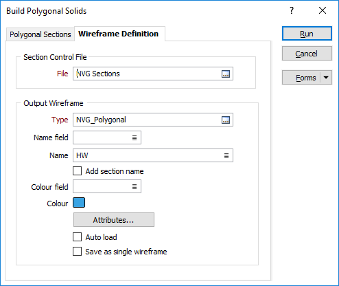
Output Wireframe
Type and Name
Specify the Type and Name of the Output wireframe. The Wireframe Type is a mandatory. A Name field or a Name default value may also be defined.
Select the Add section name check box option to append the name of the corresponding section to the name of each output wireframe.
Colour field and Colour
Optionally, set the display colour of the wireframe. A Colour field and/or a Colour default may be defined.
Attributes
Click the Attributes button to set Attributes for the wireframe output.
User-defined attributes may be mapped against the fields in the Input file. It is also possible to specify a default value for each attribute. Default values are used when a corresponding value in the Input file is either missing or is not mapped.
Set colour same as input wireframe
Select this check box to apply the colour attribute of the Input wireframe to the Output wireframe.
Save as single wireframe
Select this option to save the output wireframes as a single wireframe.
When saving as a single wireframe, if a Name attribute is not specified, the default name for the wireframe is the name of the section control file.
When not saving as a single wireframe, the wireframes are saved using an incrementing number with the section name in brackets.
Auto load
Select this option to load the generated output in Vizex. The default draw style for an auto-loaded wireframe is 3D Shaded.
Run
Click Run to run the function.