Drill Rig Options
![]()
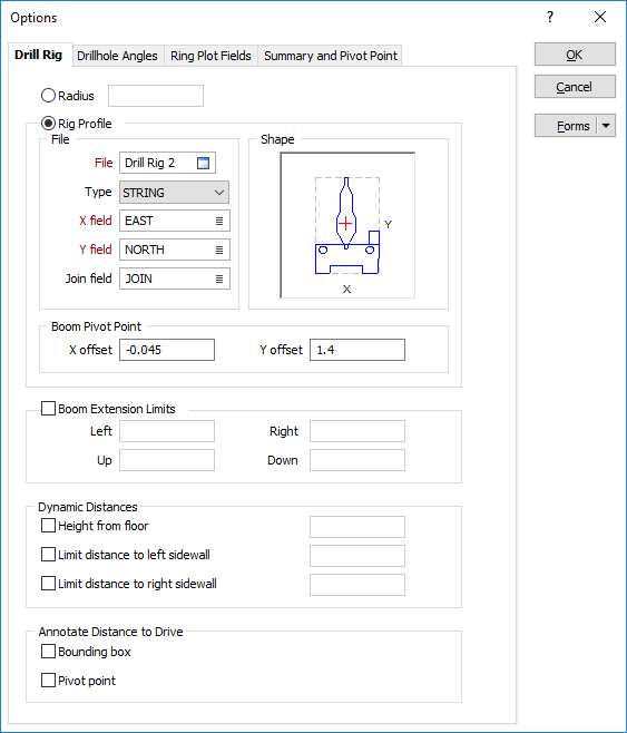
The following options are provided on the Drill Rig tab of the Ring Design Options form:
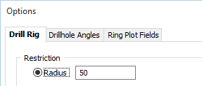
Radius
If the drill rig restriction is to be specified as a radius, specify a minimum clearance from any surface (floor, wall, or roof) that will be used to restrict the positioning of pivot points in the drives.
Rig Profile
As an alternative to specifying a radius to restrict the positioning of the rig and the rotation of the boom in the drive, you can specify a user-defined rig shape. This is achieved by using the string editing tools in the application to draw the shape, save it as a String file, and then use it as the rig outline.
The user-defined shape in the String file may be comprised of two shapes in the following order:
- one shape for the carousel or boom (rotatable)
- one shape for the rig itself (static)
When you have setup a Drill Rig Restriction in the Ring Design Options form:
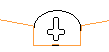
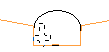
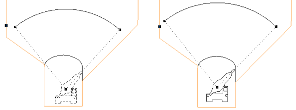
An outline of the rig shape is drawn around the cursor when new holes are designed. The rig outline is a solid line when the rig lies inside the drive (and is, therefore, in a valid position). If any part of the rig shape falls outside of the drive, a dashed line is shown.
You can use the keyboard to move or nudge the boom (the rotatable part of the rig) when designing new holes in Ring Design.
In Vizex, you can use the keyboard arrow keys to nudge selected strings or points in the plane of the screen, by a specified increment, or by a specified increment and multiplier.
The Up and Down arrows move the selected strings or points in a positive and negative Y direction. The Right and Left arrows move the selected strings or points in a positive and negative X direction.
The CTRL key can be used in combination with the arrow keys to modify the increment:
- CTRL will move by increment / multiplier.
Nudge increment and multiplier values are defined as String Editing Options (Tools | Options | Vizex | String Editing). The nudge increment defaults to 1.0. The nudge increment multiplier defaults to 10.
For example, if the nudge increment is set to 1, and the nudge increment multiplier is set to 10, the arrow keys will move the rotatable part of the rig by 1, while CTRL + arrow keys will move it by 0.1.
The rig shape can also be rotated using the arrow keys:
- SHIFT + LEFT/RIGHT ARROW keys will rotate by 5 degrees.
- SHIFT + UP/DOWN ARROW keys will straighten the rig (point the rig up/down).
- SHIFT + CTRL + LEFT/RIGHT ARROW keys will rotate by 1 degree.
Once a valid rig position is selected and the mouse button is pressed, the rig shape will be anchored at that position. As the mouse is moved around, the boom of the rig shape rotates about the boom pivot point, again changing how the lines of the rig shape are drawn.
When the pivot point and the hole angles are edited, some basic checks are made against the rig shape to ensure that the rig position/boom rotation is valid.
For fans, the boom of the rig shape continues to rotate around the boom pivot point, again being drawn as a solid line when the end hole direction is valid for the rig shape.
If you release the mouse button in an invalid rig position/boom rotation based on the hole direction, the tool will do nothing and you must select a valid direction and press the mouse button.
File
Specify the file containing the X and Y coordinates that define the shape.
Shape
The shape of the rig appears in the right-hand pane of the dialog box and is altered when you enter or modify the dimensions. The position of the pivot point with respect to the shape outline is also shown.
Boom Pivot Point
Enter the distance the boom pivot point will be offset from the shape string in the X and Y directions. The position of the pivot point is shown in the Shape pane.
Use the Drillhole Angle Options tab to specify how the hole angles are measured.
Boom Extension Limits
In practice, there is a limit on how far the boom can be offset from its default position. Select the check box to set Left, Right, Up and Down boom extension limits.
Dynamic Distances
Specify whether dynamic distances should be maintained, between the drive and the pivot point of the rig, to ensure that the boom cannot be moved too close to the roof or a sidewall:
| Height from floor | Enter a fixed distance between the pivot point and the floor of the drive. |
| Limit distance to left sidewall | Enter the minimum distance between the pivot point and the left sidewall of the drive. |
| Limit distance to right sidewall | Enter the minimum distance between the pivot point and the right sidewall of the drive. |
These distances and limits (the rig and the boom position with respect to the drive boundaries) are shown on the status bar during the process of positioning the rig.
Annotate Distance to Drive
Choose whether to annotate the distance to the drive between the Bounding box of the rig, and/or the Pivot point of the rig.