Create a drill rig profile string
![]()
When generating a ring of drillholes (see later) it is possible to take into account the size and accessibility of the drilling equipment. This safeguards against the design of holes which are inaccessible.
In order to set a drill rig restriction, the first step is to measure the dimensions of the drill rig and draw its outline using strings. By default, the drill rig is considered to be a stationary object, however its drilling equipment is a moving and rotating object (in the plane of the ring).
The drill rig outline is a cross-section (profile) of the drill rig that encompasses all of its oversize parts. The rig profile is designed using strings in Vizex. It can be drawn in cross-section view or in plan view (recommended). The coordinates of the string points do not matter, as the drawing scale is 1:1.
The String file used to define the drill rig profile may contain many strings. The first string encountered in the file (i.e. the first records of the file when it is open in the File Editor) is used to represent the mobile part of the rig. Figure 32 shows a drawing of a drill rig profile, with its movable part highlighted.
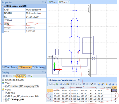
Figure 32. String of Drill Rig Profile

|
To setup a drill rig restriction for the design of your drillholes, click the Ring Design Options button on the Ring Design toolbar. |
On the Options | Drill Rig tab, select the method of applying the drill rig access restriction: using either a defined radius or the rig shape:
- If you have chosen the Radius option, specify the radius (m) of a circle which represents the minimum clearance from any part (floor, wall, or roof) of the ring boundary. If this simulated circle intersects the ring boundary, the application will not allow you to digitise a pivot point (an indication of this is the fact that the mouse cursor does not change. If a valid pivot point position exists, the mouse cursor will change to show a 'fan' icon).
- If you have chosen the Rig Profile option, specify the String file that has been created to define the rig profile, identify the X and Y coordinate fields in the file (which define the width and height of the rig), and specify the offset of the pivot point along the X and Y coordinates. You can also set Left, Right, Up and Down boom extension limits to limit how far the boom can be offset from its default position.
When you have defined the rig profile, a preview is shown on the right-hand side of the form.
An example of Drill Rig Restriction settings is shown in Figure 33.
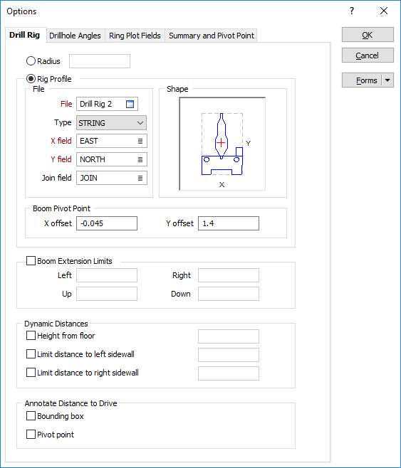
Figure 33. Drill Rig Shape Settings
When setting up a drill rig restriction in the Ring Design Options form, it is recommended that you use the Forms button to save your parameters.