Plane Grids
(An identical Convert Coordinates option is also available on the Wireframe tab, in the Editing group.)
![]()
The function assumes the scale is constant for both grids. This is appropriate where the area of interest is relatively small; up to the area covered by a 1:250,000 map sheet.
Over larger areas the curvature of the earth must be taken into account. In this case it is more appropriate to record spatial data using latitude and longitude.
Conversion methods
Two conversion methods are available:
- Two common points - you must know the coordinates of two points in both grid systems.
- Bearing correction/scale - you must know the coordinates of one point in both grid systems, the angle between the North directions of the grids, and any difference in scale.
Input methods
Three input methods are available:
- Use the Keyboard option to transform the coordinates of a few points.
- Use the File option to transform all the points in a file.
- Use the Wireframe options to transform all the points in a wireframe and optionally write them to an output wireframe.
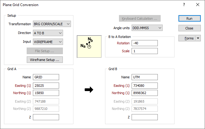
Transformation Setup
Choose the Transformation method according to the information you have at hand. If you know the coordinates of two points in both grid systems, choose 2 COMMON POINTS. If you know the coordinates of one point in both grid systems, the angle between the North directions of each grid, and the difference in scale between the grid systems (defined as a ratio), choose BRG CORRN/SCALE.
Direction
Choose either A TO B or B TO A to set the direction of the transformation.
Input
Select a KEYBOARD, FILE, or WIREFRAME Input mode.
- If you have selected the KEYBOARD input mode, you will click the Keyboard Calculation button to calculate a single set of coordinates.
- If you have selected the FILE or WIREFRAME input mode, you will click the Run button to start the transformation process.
Grid A and Grid B
2 COMMON POINTS
If you have selected 2 COMMON POINTS, enter the name of each grid and the coordinates, (Easting and Northing) of two known points in each grid system.
B to A Rotation
If you have selected BRG CORRN/SCALE, enter the name of each grid and the Easting and Northing coordinates of a known point in both grid systems.
Z
(Optional) Apply a constant Z shift value for Grid A and Grid B to ensure that all Z values are greater than zero.
Angle units
Set the (DDD.MMSS or DDD.DDDD) angle unit format for the rotation value, which is the angle between the North directions of the grids.
Enter the difference in scale between the two grid systems.
When a compound (DDD.MMSS) rotation value is entered it must be a valid compound number and take one of the following forms:
|
123 |
The rotation value only has a degrees component. |
|
123.20 |
The rotation value has degrees and minutes components. |
|
123.2040 |
The rotation value has degrees, minutes, and seconds components. |
|
123.204156 |
The rotation value has degrees, minutes, seconds, and decimal seconds components. |
To avoid ambiguity, best practice is to always enter at least 4 digits after the decimal place.
It is also good practice to set-up each grid transformation as a saved form. Transformations can then be performed quickly without having to re-enter the transformation parameters.