You can provide input to the transformation function in three ways:
- Keyboard Transform single coordinates by entering them at the keyboard (see Keyboard conversions).
- File Transform a set of coordinates in a file (see File conversions).
- Wireframe For plane grid transformations, transform a set of coordinates in a wireframe (see Wireframe conversions).
Keyboard
To transform coordinates by entering them from the keyboard:
- Set the conversion parameters as described in the conversion procedure.
- Set the Input to KEYBOARD.
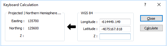
- Click the Keyboard Calculation button.
- Enter the coordinates of the point in the system for which you have values.
- Click Calculate. The values will appear in the panel opposite.
File
To transform the coordinates in a file:
- Set the conversion parameters as described in the conversion procedure.
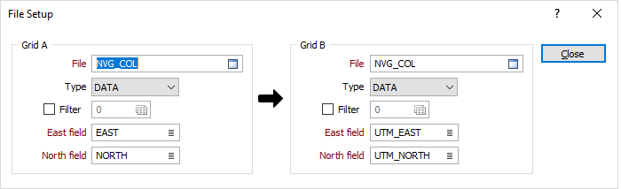
- Set the input method to FILE and click the File Setup button.
- Specify the name and type of an input file and specify the coordinate fields in the file.
If you are writing the transformed coordinates to the same file and target fields do not exist in the file, you will need to create them
- Specify the names of the fields where the transformed coordinates will be written.
- Click Close to return to the main form.
Wireframe
To transform the plane grid coordinates in a wireframe:
- Set the conversion parameters as described in the conversion procedure.
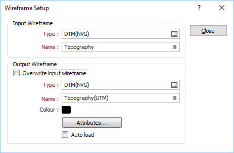
- Set the input method to WIREFRAME and click the Wireframe Setup button.
- Specify the name and type of the input wireframe.
Select the Overwrite input wireframe option if you want the result of the process to be applied to the Input wireframe. If you do not want to overwrite the coordinates of the input wireframe, specify the name and type of an output wireframe:
Type and Name
Specify the type and name of the Output wireframe.
Colour
Specify a default display colour for the Output wireframe.
Attributes
Click the Attributes button to set attributes for the wireframe output.
User-defined and Standard (Name, Code, Colour) attributes may be mapped against the fields in the Input file. It is also possible to specify a default value for each attribute. Default values are used when a corresponding value in the Input file is either missing or is not mapped.
Auto load
Select this option to load the generated output in Vizex. The default draw style for an auto-loaded wireframe is 3D Shaded.
- Click Close to return to the main form.