Adjustment Tools
When you execute a depth adjustment process, the main form has a menu bar, ribbon, and a number of right-click context menus that can be used to control the depth adjustment process.
|
|
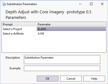
Click the Load Data button to select the data you wish to view. This will usually invoke a dialog with several substitution parameter prompts: When you load a hole from the Load button, previous tie lines are cleared.
Depending on your configuration, you may be prompted for additional information. Usually all panels will display data for the same drillhole; however, this is not a strict requirement. |
|
|
You can reload the data at any time by clicking the Reload Data button. This action will refresh the datasets without displaying the original prompts. |
|
|
Select the Save Change log option to output depth adjustments/changes to the lithology table to a separate table (GB.DA_CHANGE_LOG) so that steps taken by the adjuster can later be reviewed. Save change logs are retained for the length of time specified in the Depth Adjustment Options. |
|
|
Click the Save Changes button (CTRL + S) to save any changes you have made in the depth adjustment window. |
|
|
Click Reverse Save Order so that intervals are saved last to first. This can be used if the user is adjusting downwards. When set prior to clicking Save, the last interval is moved first, making space for the interval above it which will be saved next and so on, preventing intervals clashing into each other on Save. |
|
|
The Reverse Save Order icon provides an indication of the current (Bottom-Up or Top-Down) Save order. |
|
|
Click the Add (Insert) button to insert a tie line by entering the desired depth values for the end points in the Tie Line Editor. |
|
|
Click the Modify button to manually change the depths of a selected tie line. You can then enter the depth values for the end points in the Tie Line Editor. |
|
|
To delete a tie line, select it and click the Delete button on the toolbar, or select Delete Tie Line from the right-click menu. Alternatively, right-click and select the Remove All to select whether to delete pending, applied, or locked tie lines. |
|
|
Click the Insert into selected range button to insert a new interval into the range you define with the mouse. |
|
|
Click the Cut button to select a depth at which to cut an interval.
Using the Windows built-in Magnifier can be very useful when using Depth Adjuster, particularly when working with Images. |
|
|
Click the Insert into button to insert a new interval into the indicated interval. |
|
|
Click the Insert into gap button to insert a new interval to fill the indicated gap. |
|
|
Click the Insert above button to insert a new interval above the indicated interval. |
|
|
Click the Insert below button to insert a new interval above the indicated interval. |
|
|
Click the Fill gap above button to grow the selected interval to fill the gap above it. |
|
|
Click the Fill gap below button to grow the selected interval to fill the gap below it. |
|
|
Locked tie lines are used to limit or prevent changes to depths along certain sections of the drillhole. You can create a locked tieline by selecting the Add locked tie line button on the ribbon. A lock point is defined by creating a tie line with identical current and target depths (i.e. a horizontal tie line). This point is effectively fixed and will not be moved as a result of the depth adjustment process. To ensure that the current and target depths for a given tie line are exactly the same, select the tie line and click the Lock button on the ribbon. You can also create a lock point by holding down the Shift key when using the mouse to define the tie line. (Combine Shift with Ctrl to override snap behaviour.) Locked tie lines usually operate in pairs, effectively creating a locked section. Changes made to depths within this section will not affect intervals above or below the locked points. Two locked tie lines are defined automatically when the datasets are opened: one at zero depth and the other at the end of hole (or the maximum depth returned by the queries, whichever is appropriate). Further lock points should be added manually before any depth adjustments are made. This will ensure that the effects of the adjustments are limited to appropriate sections of the drillhole. |
|
|
Click the Unlock button to unlock a selected tie line. |
|
|
Click the Apply selected tie line button to make adjustments based on the selected tie line. When a single tie line is applied, it will adjust only those depths (in the adjustable panels) that are exactly the same as the current depth setting for the tie line. The fact that the tie line is used in isolation means that this operation has certain limitations, viz:
To adjust a depth boundary using a single tie line:
All depth boundaries that match the current depth value of the tie line will be changed to match the target depth. The display will change accordingly to indicate that the adjustments have been performed successfully across all affected panels. The colour of the tie line will change to grey, indicating that it has been applied. This tie line is now horizontal and effectively becomes a locked point. |
|
|
Click the Apply All Tie Lines button to make adjustments based on all the available tie lines. When tie lines are applied as a group, every tie line effectively becomes a control point on the depth adjustment graph. When the function is applied to the downhole data, depth readings that fall between the tie lines are interpolated from the graph (as explained in the depth adjustment overview). It is important to NOTE that all the depth boundaries in the affected panels will be adjusted according to this function. This emphasises the need for proper control via "locked" points along the depth profile. You should ensure that all tie lines are in the correct positions before they are applied. The display will change to reflect the changes caused by the adjustments. This indicates that the process has been executed successfully across all panels. The colour of the applied tie lines will change to grey to indicate their new state. The tie lines are now horizontal and have effectively become locked points. |
|
|
Click the Undo button to roll back the changes you have made in the depth adjustment window. Changes shown in the Undo Log tab (at the bottom of the depth adjustment window) can be rolled back by clicking the Undo button on the toolbar. |
|
|
Click the Add locked tie-line button to add a tie-line and lock it in one go. Locked tie lines are used to limit or prevent changes to depths along certain sections of the drillhole. You can unlock a tie-line using the Unlock button on the toolbar. |
|
|
Tie lines are used to define the control points for the depth adjustment function. A tie line links a current depth (in an adjustable source panel) to a target depth (in a reference panel). The current depth will be equal to the target depth after the depth adjustment has been performed. Click the Add normal tie line button to add a tie-line, then click on the appropriate depth in any adjustable panel, then keep the mouse button down and drag the line indicator to the corresponding target depth in any of the reference panels (or vice versa). Once the mouse button is released, the new tie line will be displayed at the appropriate position in the tie line column. To cancel the process, simply release the button while the mouse cursor is over an invalid destination panel. |
|
|
To prevent changes to the width of a selected interval, click on the appropriate depth interval (or gap), then click the Add fixed interval tie line button. The system reacts by inserting a parallel tie line at the appropriate contact of the selected unit (or at both contacts, if necessary). The system will automatically find the most suitable tie line to act as a reference (anchor) for the new tie line. If either of the contacts fall on a tie line, then this tie line will be used as the anchor. Otherwise, the closest tie line above or below the selected interval will be used. |
|
|
To create a split tie line, select the "first leg" of the tie line and then click the Add split tie line button. A split tie line is a special type of tie line that is used to insert a gap at a depth boundary. A split tie line consists of two tie lines that have the same current depth but different target depths.
Once a gap has been created, this is usually followed by an insert. The difference between this type of insert and the normal "Insert Interval" is that the split tie lines can be used in conjunction with other tie lines. In other words, the effect of the insert can be spread over several intervals, unlike a normal insert operation which affects only one or two intervals. This method ensures that the current depths for both tie lines are identical, thereby identifying the two lines as a split pair. Once this relationship has been established, the common current depth will be maintained. The split tie line can be converted back to a normal tie line by deleting either of the paired lines. A split tie line will only operate on depth boundaries that match the current depth of the tie line exactly. If there is no match, the tie line will be ignored. |
|
|
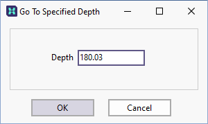
Click the Go To Depth button to move to a specified depth in the drillhole.
|
|
|
Use the Zoom option to enlarge a specified depth range. Select the zoom tool on the toolbar, then click-and-drag on the image to outline the area of interest. The selected depth range will be expanded to fit the viewing area. Click the Zoom Out button to restore the original view. |
|
|
Click the Fit To Page button to fit the entire length of the drillhole in the viewing window. This action will automatically turn off annotation to avoid clutter. (See "Annotation button" below). |
|
|
Click the Original Scale button to restore the page to its original scale. |
|
|
Select an option from the Scale Bar Settings tool menu to Scalebar Settings or restore the original scale of depth adjustment window. |
|
|
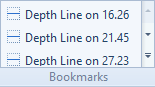
Click the Show Bookmarks tool to enable or disable the display of bookmarks. When the tool is enabled you can insert horizontal lines using CTRL + Left mouse click, or by pressing CTRL + Insert after digitising a position point. The horizontal lines you add are listed in the Bookmarks panel in the ribbon. You can navigate to a particular depth by selecting a depth from the list.
Note that when you turn off the Show Bookmarks tool, all bookmarks are deleted. To delete a particular bookmark, simply click on it with the mouse. |
|
|
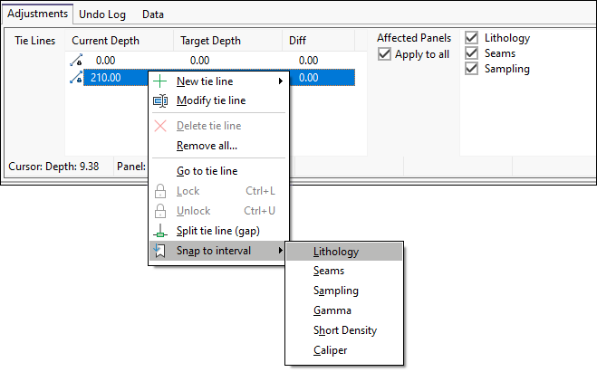
By default, the start and end points of a tie line will "snap" to the nearest depth boundaries in the source panel when the tie line is created; however, if you drag the line indicator to the corresponding target depth in a reference panel of type Column, they will snap to the nearest depth boundaries in that reference panel. You cannot snap to a reference panel of type Graph. In some cases, snapping to the nearest depth boundary may not be the desired behaviour. You can toggle the snap tool on and off by clicking the Snap button on the toolbar. Alternatively, you can temporarily disable the snap tool by holding down the CTRL key before clicking the mouse button to define the tie line. The currently selected tie line can also be snapped manually by using the Snap to interval options on the right-click menu. Choose the panel to snap to from the list provided in the sub-menu.
|
|
|
To toggle the annotation on and off, click the Show Annotation button. Clicking the Fit To Page button (See Above) will automatically turn annotation off. |
|
|
To toggle the display of static horizontal lines across the width of the drawing canvas for the purpose of checking depth alignments, click the Show Depth Grid button. |
|
|
Toggle the Show Scale Grid button to show the horizontal scale labels between the start and end points and show vertical grid lines below each scale label. The header section will expand to accommodate the labels.
|
|
|
To enable the rendering of tie line shoulders over all panels, click the Show Extended Tie Lines button. Click the button again to disable the function. |
|
|
To stretch the Depth Adjustment panel horizontally to fit on a single screen, click the Enable Stretch Panel button. You can toggle the stretch panel off by clicking the button again. |
|
|
To enable the display of highlighting for the panel under the cursor, click the Enable Panel Highlight button. Highlighting the panel is useful for snapping operations, and can be toggled off using the button. |
|
|
Click the Windows button to navigate between different Micromine Geobank windows. |