Grids
This
When you right-click on the Grid node or a Grid folder or a Grid in the Design Data pane, you can now select an option to Convert to Reference Grid(s).
When you convert a project grid to a reference grid, the grid data is no longer stored in the project/model database. Instead, the grid data is loaded directly from a referenced (*.grd) file.
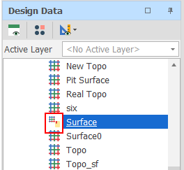
Minex grid file (*.grd) format is the default conversion format (since this is a format that ensures rotation support). To differentiate between project grids and reference grids, the icon alongside the name of each converted grid is changed:
![]()
![]()
![]()
A design_reference_grid_readonly setting toggles whether the mesh of a reference grid can be mutated. If a reference grid mesh is mutated, any changes to the mesh are saved to the referenced file whenever the project is saved.
When you delete a reference grid in the Design Data pane, only the reference to the grid file is removed. The grid file itself is not deleted.
Individual reference grid files or multiple reference grid files in a folder and subfolders can be re-imported. You can also select an option to convert reference grid files back to project grid files:
![]()
![]()
![]()
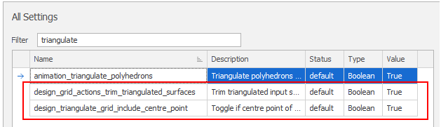
To reduce memory usage and avoid out of memory exceptions when working with very large grids, the following settings are available in All Settings:
-
design_triangulate_grid_include_centre_point
The default setting (True) is fine for smaller grids. The use of includeCentrePoint in GridMesh.Triangulate increases the fidelity of the triangulation at the cost of a significant increase in the size (number of points and vertices) of the triangulation.
If you are working with large grids, it is recommended to change this setting to False to reduce the size of triangulated grids.
-
design_grid_actions_trim_triangulated_surfaces
The default setting (True) is fine for small input meshes and ensures that the size of the triangulated grid is only as big as is needed by the input data it is working with (for example, from the triangle mesh that is being clipped).
This can result in a significant reduction in the size of the triangulated grid. However, if trimming is causing issues or is running too slowly, change this setting to False.
When the Design Window is open, new grid utilities are now available for selection on the Grid tab, in the Utility group:
-
Click Adjust Stratigraphy to adjust the grids in a stratigraphy to conform to layering requirements. (Ctrl+Alt+A,T)

-
Click Clip Grid by Polygon to clip a grid by a set of polygons. (Ctrl+G,C)

-
Click Expand Grid to expand a grid outwards by a specified amount. (Ctrl+Alt+G,A)

-
Click Register Grid to register a grid to another grid. (Ctrl+G,A)

-
Click Fill Grid Holes to find and fill the holes in a grid. (Ctrl+G,H)

Add New
When the Design Window is open, you can now right-click on the Grids node in the Design Data pane to add a new empty grid to the Design Data:
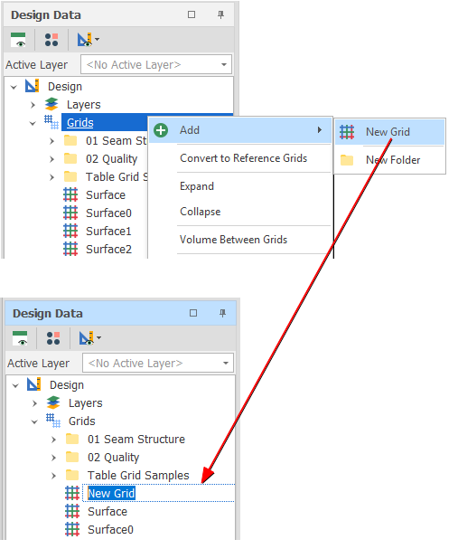
Design Data > Grids > Add > New Grid
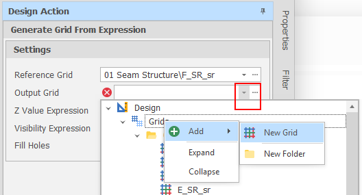
You can also add a new (empty) grid when you select the Output grid in various (Create Surface, Generate Grid From Expression, Register Grid, Expand Grid, Fill Grid Holes) grid-related actions and utilities.
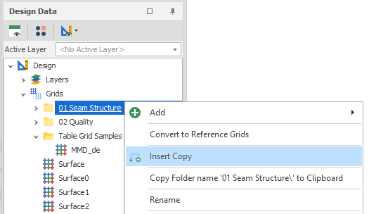
Insert Copy
In the Design Data pane, you can now run an Insert Copy Command on a single or multiple selected grids. You can also Insert Copy a folder containing multiple grids (but not multiple selected grid folders).
On the Grid tab, in the Add group, when you click Create Surface to create a surface grid from design elements currently visible in the Design Window, you can now set the (Fast, Accurate) precision of the gridding process.
Accurate is the default mode of precision. The gridding algorithm will attempt to maintain precision for small regions. This is achieved by sampling an area that is the size of the data extents. Additional data points outside the selected region are then ignored when creating the grid.
Fast may be preferable when a large region (relative to the size of the data extents) is selected.