Define a Section
The Section tool is used to define a section within an object in the Viewer.
When a section is defined, the Section View toggle is used to enable or disable Section view.

On the Navigation bar,
-
Select Viewer.
-
Open the object for the section to be defined in the Viewer.
-
Select the Section tool.
-
Click on the starting coordinate in the grid from which you want to define the section.
-
Move the cursor to the required end point of the section, and rotate the section rectangle if required, then click.
Note: If you need to redefine the start point of the section before completion, press Esc (or right-click) and try again.
Tip: Use CTRL to snap to angular steps (0-30-45-60-90⁰).
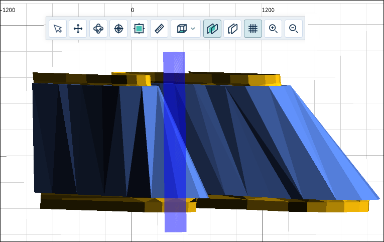
When you click the end point, the section is defined as a transparent rectangle:
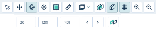
Once the section is defined, the Section tool settings will be displayed.
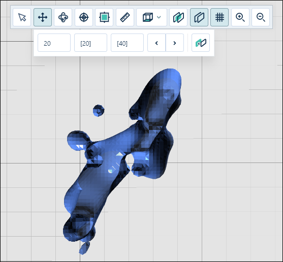
The object in the Viewer will also be placed in Section View mode. You can toggle this view off and on using the Section View button.
The Section tool options allow you to set the Towards, Away and Step values (in metres).
In Section View, Towards is a measurement taken from the section line towards you, the viewer. The value in the Towards field sets the visible width in front of section plane.
Away is a measurement taken from the section line away from you, the viewer. The value entered for Away sets the visible width behind section plane.
The default values for Towards and Away are 20 and 20.
The Step value is the distance to be moved through the section view. The default value for Step is Step = Towards + Away, in this case 40, but this can be customised to any required step value.
If you enter Away or Towards values, the Step value is automatically updated. Once you have entered a custom Step value, it will no longer be automatically updated.
You can use the arrow buttons to navigate through each Step in the section view at the distance specified.

While Section View is active, you can use the Plan View options to view the section in the available perspectives; Looking Up, Looking East, Looking West, Looking North and Looking South. You can also rotate, move and zoom the section view as normal.
The Align button in the Section tool options is used to align the view to the current section plane.

If required, you can use the Vertical Exaggeration control at the bottom right of the Viewer to set a vertical exaggeration for the section:
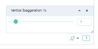
Adjusting the vertical exaggeration is useful when visualising large areas with short traces and a very small Z range such as alluvial ore bodies and stratiform deposits such as coal. Without an adjustment to the Z dimension, it is sometimes difficult to recognise that there are two polygons very close together.
-
To exit Section View, toggle it Off.