Three-centred Arch
The 'Three-centred arch' is a common drift design method which can be selected as a Profile Shape option in the Centreline to Solid (form) form.
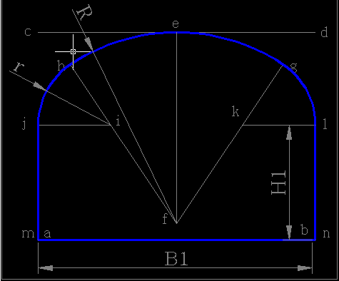
The following diagram shows the parameters and how they are included in the calculation to arrive at a three-centred arch shape.
The three-centred arch calculation is as follows
- Inputs are the designed drift excavation width (B1) and the designed drift excavation height (H1).
- Draw a horizontal line ab with length of B1; draw another horizontal line cd above it with the same length and offset from line ab by H1+B1/3. Make a vertical line ef with a length of 0.692 B1 starting from point e which is the midpoint of the line cd.
- Make point f the centre with a radius of 0.692 B1 and draw an arc hg anticlockwise with an angle of 66 degrees and 82 seconds starting from an azimuth of 33 degree 41 seconds.
- Point i is on line hf, a distance of 0.262 B1 offset from point h. Make point i the centre with a radius of 0.262 B1 and create an anticlockwise arc with an angle of 56 degrees and 19 seconds, starting from point h and ending at point j.
- Point k is on the line gf, a distance of 0.262 B1 offset from point g. Make point k the centre with a radius of 0.262 B1 and create a clockwise arc with an angle of 56 degrees and 19 seconds, starting from point g and ending at point l.
- Make point j the starting point and draw a vertical line down to point m. The length of the line jm is H1. Making point l the starting point and draw a vertical line down to point n. The length of the line ln is H1.
- The closed area consists of lines ln, nm, mj and arcs jh, hg, and gl. Together they comprise a 'three-centred arch'.