3D View
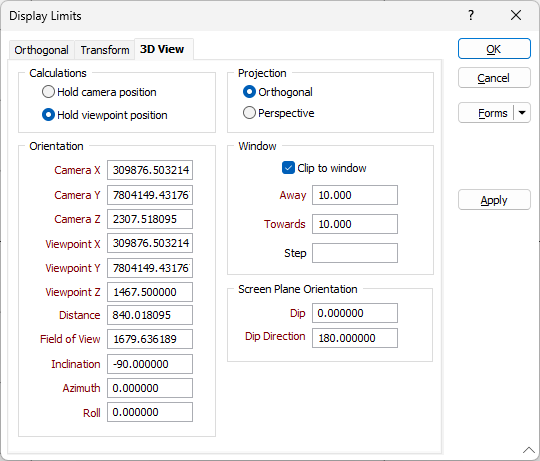
Use the 3D View tab of the Display Limits form to view the limits of the display in 3D.
Calculations
3D objects can be viewed from different positions and angles by rotating and moving the camera, not by rotating and moving the objects, although that is what appears to happen.
When you select an object and rotate it, you are actually moving the camera through the space.
When adjusting the 3D display, specify whether to Hold the camera position (where you are looking from) and adjust the viewpoint (the focal point of the camera as determined by its orientation), or whether to Hold the viewpoint and adjust the position of the camera.
Orientation
Use the settings displayed under Orientationto set the camera position and orientation.
- Camera X ,Y ,Z parameters can be set to reposition the camera when you want to view an object from a different angle or position.
- Viewpoint X ,Y ,Z parameters are used to look at an object from a cardinal direction. These settings determine the orientation of the camera.
- Distance and Field of View settings apply when using a perspective camera. Setting a distance is equivalent to 'dollying' the camera in and out. The Field of View is specified in degrees from 1.0 to 140.0 (default 45.0). The camera position is not changed, but its angle is widened or narrowed.
- Inclination, Azimuth, and Roll define the orientation of the camera. Changes made to these parameters will the affect the viewpoint X, Y and Z and vice versa.
The vertical viewing angle (for a horizontal view = 0. Inclination is measured in degrees from the horizon. Positive values are looking up and negative values are looking down).
The (horizontal) viewing direction (with Looking North = 0. Azimuth is measured in degrees clockwise from north).
In real life, a measure of how much your head is tilted. Using an aviation analogy, Azimuth is the heading (relative to north) of the plane, Inclination is its angle of ascent or descent and Roll is how far the wings are off horizontal.
Projection
Two cameras are available for use with the 3D display:
![]()
The Perspective camera emulates the human eye, that is, objects that are further away appear smaller. This is the most commonly used camera.
The Orthogonal camera produces parallel projections and thus does not create a distortion with distance. Use it when it is important to get an exact idea of measurements, which would be distorted with the Perspective camera.
Window
Clip to Window
Select the Clip to window option to restrict the display to a window which is defined using measurements towards and away from the current Z value.
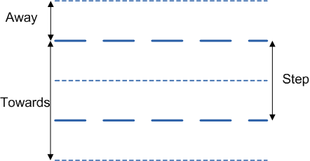
Window Towards and Away
The values you enter in Window towards and Window away define the width and position of the data corridor (the “thickness” of the slice).
- In Plan view, Window towards is a measurement taken from the nominated level towards the viewer. Window away is a measurement taken from the nominated level away from the viewer.
- In Section view, Window towards is a measurement taken from the section line towards the viewer. Window away is a measurement taken from the section line away from the viewer. See Window Towards/Window Away
If you have not previously set default Away and Towards values, the default values specified in the Clipping tab of the Tools | Vizex | Options form will be shown.
A preview of the section line is displayed in the preview pane, based on the parameters you have entered.
Step
In the Step input box, set the distance to be moved from the Next Section/Previous Section.
If Step = Away + Towards
This is the default step value, which is shown on the Home tab or the Vizex tab, in the Section group . Whenever you change the Away or Towards values, the Step value is automatically updated.
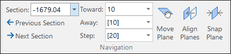
As long as Step = Away + Towards, the Step value on the Display Limits form is left blank until the user specifically enters a value.
But what if you want to increase the Window Towards value and keep the Step value unchanged so that you can, ![]() for example, step to the next section but still see the previous section?
for example, step to the next section but still see the previous section?
If Step <> Away + Towards
This is a non-default step value, which is shown on the Home tab or the Vizex tab, in the Section group without square brackets. If you change the Away or Towards values, the Step value is not updated.

When Step <> Away + Towards, the Step value is shown on the Display Limits form.
Screen Plane Orientation
Enter Dip and Dip Direction values to set the orientation of the screen plane.