Tools
Tools applicable to underground ring design are available on the Mining | Ring Design tab. To enable the ribbon you will need to select a Ring Design layer as the Active Layer.
Not all the tools on the ribbon will be enabled. The Create Boundary tool, for example, will be disabled until you select Edit | Edit Ring to enter Edit Ring mode.Conversely, Add Drive, Set Drive Wireframe, and Create New Ring tools are unavailable when you are in Edit Ring mode.
Create
-
Select Display Layers | Mining | Ring Design to open a Ring Design layer.

Edit
Use the tools on the Mining | Ring Design tab, in the Edit group, to Add Drive, Add Rings, or Edit Rings in the current Ring Design layer.
-
Click Add Drive to add drives to a ring design interactively using the drive strings and boundary wireframes you have loaded in Vizex.
![]()
-
Select Add Drive (form) to add drives using the drive strings in a nominated String file, and the drive profiles in a nominated Drive Boundary Wireframe.
![]()
-
Click Create New Ring. Before you create a ring you will need to select an existing drive in the display, or add a drive to the display.
![]()
-
Click Edit Ring to put the display into Edit Ring mode.
![]()
-
when the display is in Ring Edit mode, click Edit Previous Ring or Edit Next Ring, to step through and edit the previous or next rings (by chainage) on the current drive.
![]()
![]()
-
Click Replicate Ring Along Drive to copy a ring along the drive multiple times.
![]()
-
Click Copy Ring to copy the currently selected ring to a new location on any drive. Once in Copy mode, you can select a point on any drive (including the drive the source ring is located on) as the location for a new ring.
![]()
-
Click Delete Selected Ring Design Object (or press the DELETE key on the keyboard) to delete all currently selected (drive, ring, or hole) objects.

-
Click Delete Drillholes from Selected to delete holes by selecting one or more (drive and/or ring) objects which contain the holes you want to delete. You can use this tool without necessarily entering Edit Ring mode.
![]()
-
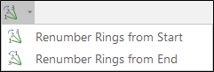
when a ring is selected (Edit Ring mode is not active) the option to Renumber Drillholes in both directions is provided.


In Edit Ring mode:
-
Click Renumber Drillholes to renumber the holes on the current ring.
![]()
-
Click Centreline to Solid to convert one or more strings into a wireframe - for example, to generate a single wireframe, or generate multiple wireframes, from the polygons that define underground features such as drives.
![]()
-
On the Profile Shape tab of the Centreline to Solid (form), set the parameters of the profile shape for the wireframes that will be generated from the polygons you have selected in Vizex. Options to generate wireframes per polygon, per segment, or split by parts or length, are provided in the form.
![]()
Visualise
Use the tools on the Mining | Ring Design tab, in the Visualise group, to navigate and manipulate the display.
-
when the display is in Ring Edit mode, click View Previous Ring or View Next Ring, to toggle the display of the previous or next ring.
![]()
![]()
-
Click Mirror Ring to mirror the current ring. You must be in Edit Ring mode to access this option.
![]()
-
when the display is in Ring Edit mode, click View Ring Plane to change the orientation of the display so that it is orthogonal to the selected ring plane.
![]()
Boundaries
Use the tools on the Mining | Ring Design tab, in the Ring Boundary group, to create or edit a ring boundary, use wireframes to auto-generate boundaries, or apply a boundary shape in a polygon file.
-
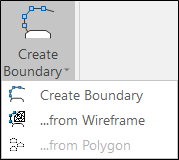
Click Edit Boundary to create or edit a ring boundary. If the display is not already in Edit Ring mode, the display will enter Edit Ring mode.
When you create a ring boundary, the string is automatically closed as a single regular polygon which completely encompasses the drive.
![]()
-
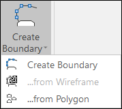
Click From Wireframe to generate ring boundaries automatically using the 2D slices of the stope wireframes located at the position of each ring along the drive. The tool is applied to selected rings along the drive, or if you have selected a drive string, all rings along the drive.
-
: When the display is in Edit Ring mode, click From File to apply a boundary shape in a polygon file.
Drillholes
In Edit Ring mode, use the tools on the Mining | Ring Design tab, in the Drillhole group, to interactively edit or adjust drillholes, generate an angled or a parallel fan, generate an angled drillhole or an offset drillhole, and renumber drilholes.
-
Click Generate Fan to create an angled "fan" of holes.
![]()
-
Click Generate Parallel Fan to create a group of parallel holes within an extent rectangle.
![]()
-
Click Generate Angled Drillhole to add a hole to a ring (by defining a pivot point and an end point with the mouse).
![]()
-
Click Generate Single Offset Drillhole to add a hole to a ring, in a position which is relative to another hole.
![]()
-
Click Adjust Drillhole Lengths to shorten or lengthen holes.
![]()
-
Click Edit Drillholes to modify the position of multiple drillholes and/or pivot points whilst maintaining the toe boundary distance.

-
Click Adjust Multiple to auto-adjust multiple holes relative to (the manually adjusted) position and orientation of a single reference hole.
![]()
-
Click Renumber Drillholes to renumber the holes on the current ring.
![]()
![]()
-
Click Show Drillholes to display either Planned or As-drilled drillholes in the ring, both Planned and As-drilled drillholes, or None.
Planned: 
As-drilled: 
Planned AND As-drilled: 
NONE: 
Charging
In Edit Ring mode, use the tools on the Mining | Ring Design tab, in the Charging group, to apply charging and stemming to the holes on a ring using a chosen calculation method, define the charged and stemmed intervals for a hole, and calculate a charge energy distribution grid
You can also auto-charge the holes on rings using wireframes or polygons to define the charge zones, without entering Edit Ring mode.
Note: Any charging and stemming settings should be verified by a mining engineer prior to the creation of a blasthole layout.
-
when the display is in Edit Ring mode, click Calculate Charging & Stemming to automatically load the holes on the ring and apply a charging algorithm.
![]()
-
when the display is in Edit Ring mode, click Calculate Charging & Stemming to use the mouse to adjust the charged and uncharged (stemming) interval lengths for individual holes. If holes have been deck charged, then multiple stemming and charge intervals may be adjusted.
![]()
-
when the display is in Edit Ring mode, click Assign Intervals to enter or edit the stemming and charge interval lengths for a selected hole.
![]()
-
Click Charge Exclusion Zones to auto-charge the holes on rings using wireframes or polygons to define the charge zones. The function allows solids and polygons to be selected for multiple rings in 3D mode (including section view) or in Edit Ring mode.
![]()
-
when the display is in Edit Ring mode, click Charge Energy Distribution to generate a charge energy distribution grid that can be used to validate ring patterns and their explosive charging.
![]()
Setup
Drill Rig Options and Ring Plot Options are available on the Mining | Ring Design tab, in the Setup group.
-
Click Drill Rig Options to set drill rig position settings and display options.
![]()
-
Click Ring Plot Options to set ring design plot options.
![]()
Reports
Use the tools on the Mining | Ring Design tab, in the Report group, to generate Ring Design Plots and Reports.
- Click Ring Wireframe Report to generate wireframes which represent the area that will be blasted for either the current ring, or all of the rings on the selected drive. You also have the option of estimating tonnes and grades for the blasted area.
![]()
-
Click Generate Ring Plot to generate a Ring Plot.
![]()
-
Click Generate Batch Rings Plot to generate a batch of plots for multiple rings.
![]()
-
Click Report to generate a database and drive summary report.
![]()
Import/Export
Ring Design Import and Export functions are available on the Mining | Ring Design tab, in the Import/Export group.
-
Click Import IREDES to import a Ring Design in IREDES file format.
![]()
-
Select Import Surveyed Holes to Import survey data (collar and toe locations) manually collected manually in the field.

-
Click Export IREDES to export a Ring Design to IREDES file format.
![]()
-
Click Export Ring Design to convert a Ring Design to a Drillhole Database (DHDB) format.
![]()
-
Click Set Drive Wireframe, to update the profile of a ring design drive. A typical use case of this tool would be to update the geometry of an as-planned ring design to reflect as-blasted data when it becomes available.
![]()
-
Click Export Drive Wireframe, to generate a wireframe and save a selected drive and centreline string file for the selected ring design drive.
![]()
Template
-
Click Save Template to save the drillholes in a ring to a (*.MMHDFTEMPLATE) template file.
![]()
-
Click Load Template to load a (*.MMHDFTEMPLATE) template file containing the drillholes in a ring.
![]()
Search
-
click Find to find ring design objects using wildcards and/or regular expressions, and optionally zoom to selection.
![]()
Pin
Click the Pin icon to display the ribbon even when it is out-of-context (in other words, the Vizex layer or the editor or function it relates to loses focus or is closed). The ribbon will be displayed until you either click the icon again to unpin it, or Close it.

Close
Click Close to close the ribbon. The ribbon is displayed automatically when it is in-context (in other words, the Vizex layer it relates to is opened as the active layer, or the editor or function it relates to is opened.

Save your changes
You must explicitly save any changes you make to the objects in the Ring Design layer. This applies when you edit rings, drillholes, and ring boundaries. If you do not save your changes, you will be prompted to do so when you either close the display layer, exit Vizex, or exit the application.