Guides
On the Guides tab of the Pit Design Setup form you can configure the guides for the pit design using an optimised shell boundary.
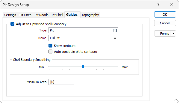
Adjust to Optimised Shell Boundary
When the Adjust to Optimised Shell Boundary option is enabled, the projected pit design strings are automatically adjusted to match the limits of an optimised pit shell.
Type
Double-click (F3) to select the type of the pit shell wireframe.
Name
Double-click (F3) to select the name of the pit shell wireframe.
Show Contours
Select the check box to display the contours for the shell boundary.
Auto constrain pit to contours
Select the check box to automatically constrain the pit design to the displayed contours.
Shell boundary smoothing
A Loose (Polynomial Approximation) smoothing method smooths the shell boundary based on a smoothing tolerance that controls the length of a "moving" path used to calculate new vertices. The curve does not pass through any of the vertices of the original strings or segments, except the first and last.
Use the slider bar to determine the degree of smoothing of the design strings. Setting the smoothing slider to a higher setting will ensure that the strings are free of jagged/sharp segments and better satisfy minimum mining widths.
Minimum Area
Optionally enter a Minimum Area for the contour in the field provided. If no value is entered, the default of 0 will be applied (i.e. no minimum area).