Points & Lines
The Points and Lines tab of the Import CAD form is enabled if the input file contains point and line features. Select the Import Points and Lines check box to enable the import.
File
Enter (or double-click (F3) to select) the name of the target file to which the point and line data will be written.
Folder path
In Bulk import mode, the Folder path is required. The destination folder will default to the project folder (shown as [Auto]). You can specify another folder if required. Each CAD file is imported the specified folder as its own file of the same name.
In Single file mode, if you select the Save a file for each layer option, separate files will be created per CAD layer. The File field will change to the ‘Folder path’ field (as in Bulk mode) and you can specify a folder for the output files. Output files are given the same name as the Input file, with the layer name appended on the end with an underscore “_” separator.
In Bulk mode, the Folder path field is available to specify the folder where files for each CAD layer in the input file will be saved.
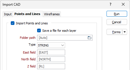
Easting, Northing, Z fields
Specify the names of the fields to which X, Y and Z coordinates will be written.
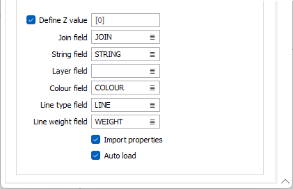
Define Z value
Select this option to define a Z value for the imported points and lines.
Join field
(Optional) Specify the name of the field containing values which define whether data points will be joined by a line i.e. strung. If successive records have the same value in this field and no String field is defined, a line will join the points. If a String field is defined, then values in each field in successive records must be the same before the points will be strung.
String field
(Optional) Specify the name of the field containing values which define whether data points will be joined by a line. The values of this field in successive records must be the same before the points will be strung.
Layer field
Specify the name of the field that will contain values which can be used in subsequent file operations to filter the data based upon a particular feature type (layer).
During import, the AutoCAD layer name is written to this field. The import process will enumerate through the layer names to obtain a maximum width for the field.
Colour field
(Optional) Specify the name of the field to which the imported point and line colours will be written. These values will be used to colour-code the display when the Auto load check box option is selected.
The selected field must be a formatted Colour field.
Import Properties
Select this option to include the attributes for the CAD files when importing.
Auto load
To display the data in Vizex once the file(s) have been imported, select the Auto load option.
If the input file contains 3D solids that can be imported as wireframes, use the Wireframes tab to configure the import process.