Output
On the Output tab of the form, specify the type and name of the Output file.
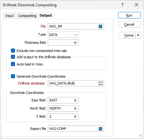
File
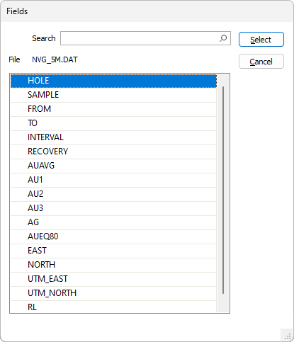
Double click (F3) or use the Select icon in the File field to navigate to and name the output for the compositing. If you select an existing file, you will be asked to overwrite or append it.
Thickness field
If you want to link calculations to a key field, you must specify a Thickness field on the form. This field is used to calculate the thickness of the rows that were skipped (if any), based upon the calculations that were performed during processing. The 'skipped' thickness is compared against the minimum composite length.
Double-click to display a list of the fields in the input file and select the field where the thickness values will be written.
If specified, the differences between the From and To values for each interval in the output file will be written to this field.
If a Thickness field already exists, the functions will process the thickness values, apply the default compositing method, and write composited values to an identical field in the output file.
Exclude non-composited intervals
Select this option to only write intervals that are included in the compositing process to the output file.
Add output to the drillhole database
Select this option to automatically add the composited output file to the drillhole database specified below.
In many cases, it may be useful to store the results of the compositing process to the database that the input interval or assay file is associated with. This aids in visualisation, making it easier to display related downhole data in Vizex.
Auto load in Vizex
Select the check box to automatically load the composite output file in Vizex.
With the option enabled, a hatch layer will be loaded with the To field used for the Foreground Colour value.
If a Constant field 1 is used, the field name in the Constant field 1 box is set as the Colour field and the palette is set to Discrete-Bright with Unique assignmentenabled.
The Auto load option will only be available if Add output file to drillhole database has been selected.
Generate Downhole Coordinates
Select this option to define trace coordinates and write those coordinates to the specified drillhole database.
Specify a value for the East field, North field and Z field options or accept the [Auto] defaults to auto-generate the field names.
3D coordinates are needed whenever an Interval file is used in a process where the locations of the intervals must be known, for example, resource estimation assignments using polygons.
Drillhole Database
Double-click (or click on the Select icon) to select from a list of drillhole databases in the current project.
Press F5 to create a new drillhole database. Press F4 to edit a drillhole database you have selected.
Report file
Enter the name of the Report file. If any errors occur during the process, they will be written to this file. See: Errors in the Compositing process
Forms
Click the Forms button to select and open a saved form set, or if a form set has been loaded, save the current form set.
Run
Finally, click Run to begin the process.