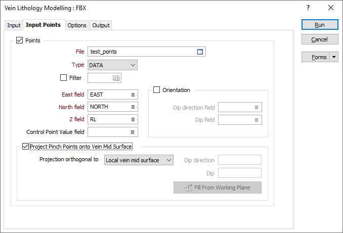
Input Points
Use the Inputs Points tab to specify a set of points that can be used to constrain the surface of the
Note: Zero-valued extra input points are treated as pinch points, independent of the When vein code is missing option on the "Options" tab. That is, if zero-valued extra input points are specified, and "Ignore" is selected for the When vein code is missing option, then the vein will pinch as the locations indicated by the extra input points, but not where drillholes do not contain any contact intervals.
Points
Select this check box to constrain the modelling process so that surface of the model is coincident with a set of input points.
File
Double click (or click on the Select icon) to select an Input file. Typically, the Type of the Input file will be a DAT file containing point sample data. Other file types are also supported; including Survey, Structure and Report. You can optionally apply a Filter to the records in the file.
East, North and Z fields
Specify the names of the fields in which Easting, Northing, and Z coordinates are stored in the Input points file.
Orientation
Use the inputs to include structural information (dip and dip direction) to points, and the
Double-click (or click on the List icon) to select the name of the Dip direction field.
Double-click (or click on the List icon) to select the name of the Dip field.
Control Point Value field
Optionally, select the field in the Point file where the control point value is stored. If a field name is specified, the value contained in the field will determine the behaviour of the Vein model:
-
Positive values (+1) will modify the hanging wall surface of the Vein model.
-
Negative values (-1) modify the footwall surface of the Vein model.
-
Zero (0) values represent pinch points in the model, which forces the application to pinch the Vein at that point.
-
If the field value is left BLANK for individual records in the input DAT file, then those input points will not control the location of the Vein surfaces.
Project Pinch Points onto Vein Mid Surface
Select this option to choose one of the following plane projection options:
| Option | Description |
|---|---|
| Local vein mid surface | Pinch points are projected orthogonally to the vein mid surface, according to its local curvature. This is the default option. |
| Plane of pinch points | The projection direction is orthogonal to the plane of best fit of the pinch points. At least 3 pinch points must be present. |
| Custom plane | The projection direction is orthogonal to a plane defined by a user-supplied Dip and Dip Direction. If a suitable display layer is open, these can be automatically filled from a working plane in Vizex by clicking the Fill from Working Plane button. |
| Plan View | Pinch points are projected vertically. |
| Looking North view | Pinch points are projected in the north-south direction. |
| Looking West view |
Pinch points are projected in the east-west direction. |