Input
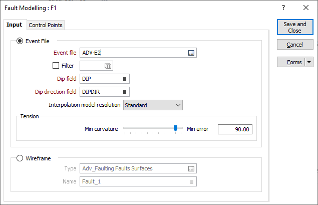
On the Input tab of the Fault Modelling form, choose whether the input to the fault modelling process will be an Event file or a Wireframe.
Event File
Double-click (or click on the Select icon) to select the name of the Source file containing the fault data you want to use in the fault modelling process. Optionally, define a filter to restrict the process to a subset of the data in the file.
A wireframe will be generated which represents the fault structure.
Fault Code
Select a field in the Event file that contains the values which identify each fault (e.g., F1, F2, F3, etc.).
Dip and Dip Direction fields
The orientation of the generated wireframe(s) is dependent on the Dip and Dip Direction of the points in the Input file. Specify the fields in the Input file which contain a dip and a dip direction for each point.
The dip values in the Input file should be 0-90. Dip direction values should be 0-360. Any values outside of these ranges (i.e. negative dips) are ignored and a warning message is displayed after processing is complete.
Interpolation Model resolution
Select a Standard, Fine or Superfine resolution for the output model. The option you select will determine the size of the blocks (grid spacing) for the area of interpolation.
Note that the Fine and Superfine interpolation resolution options may require a modelling parameter file to be stored in your Windows Temp directory and may take up to 1.5GB of space.
Tension
Use the slider to set a tension value between 0 and 100, where smaller values favour smoothness (minimum curvature) and larger values favour accurately honouring the contacts (minimum error). The default is
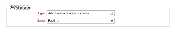
Wireframe
Double click (F3) or click the ellipsis in the Type field to select a wireframe type and then click the List button to select a wireframe that represents the fault structure you want to model.