Blast Design
This
Adjust to Topo
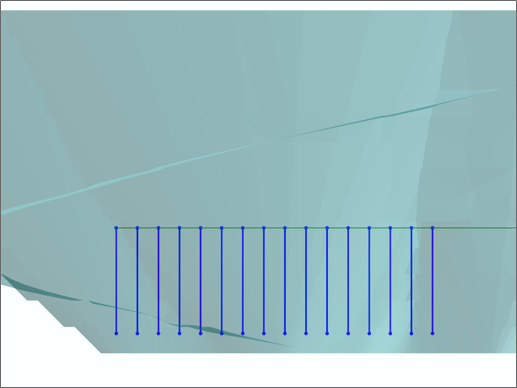
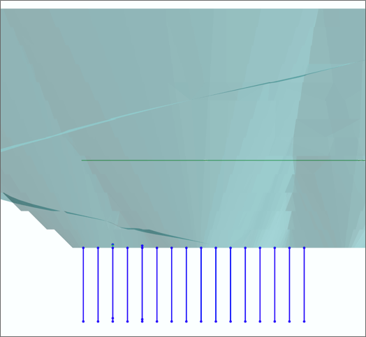
On the Mining | Blast Design tab, in the Modify group, you can now select an option to adjust blasthole depths by draping blastholes onto a surface that lies above or below the collars of the holes, in the current plane of the view.
| Before: | After: |
|
|
Colour & Label Options
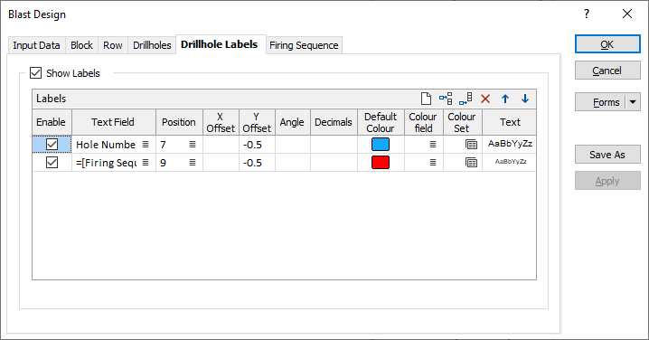
On the Drillhole Labels tab of the Blast Design form, enhanced hole labelling (Position, Colour, Offset, Text, etc) options now facilitate the creation of more visually appealing technical reports.
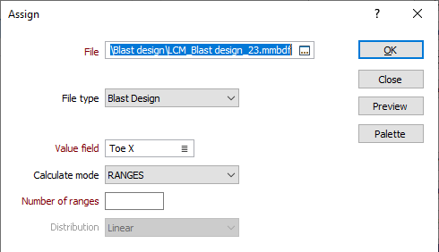
When assigning a colour set to the labels, the Assign function will now automatically default to "Blast Design" as the file type and pick up the name of the Blast Design Database and the Colour Field chosen on the Drillhole Labels tab of the form.
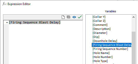
The use of Expressions in the Text field and the selection one or more Blast Design variables are also supported.
Hole Distance to Free Face
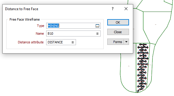
On the Mining | Blast Design tab, in the Report group, a new Distance to Free Face tool can be used to check that the designed holes adhere to a specified minimum distance to the free face.
![]()
If necessary the collar position, inclination and orientation of a hole can then be edited interactively. An annotation of the current distance to the free face is shown.
Add In-fill Holes
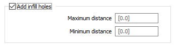
On the Mining | Blast Design tab, in the Drillhole Pattern group, when you click Rectangular Pattern to create a blasthole pattern within the bounds of a polygon, you can now select an option to add infill holes.
After designing a drillhole pattern, an engineer will typically look for empty regions near the corners and ends of the pattern, where the nearest hole may not provide enough energy to break the rock. For example, the hole spacing is 5 metres, the Spacing Offset Distance is 2 metres and the distance between the last hole in a row and the bounding polygon is 4.85 metres. In this case, an infill hole is added.
If specified, Minimum and Maximum distance values are used as the radii of two circles drawn around the first and last holes. If an adjacent hole is not detected within the radii, then an infill hole is added to the start/end of the row, taking into account the Spacing, the Spacing offset (if any) and the value entered in a new Minimum Distance to Boundary parameter (if any).
Merge Rows and Blocks
On the Mining | Blast Design tab, in the Drillhole Pattern group, new Merge options allow the rows and block of a blast design to be merged together.
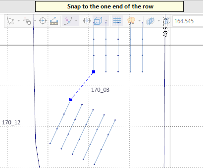
Merge Rows works by manually snapping from the end of one row to the start of another row or vice versa.
![]()
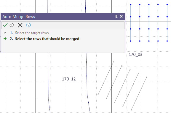
Auto Merge Rows. The Selection Assistant prompts you to select the target rows and then the rows to be merged. The corresponding rows in each selection group are then merged using a shortest distance algorithm. The behaviour of the auto merge will depend upon the order or direction in which the rows are selected in each group, which should correspond.
![]()
If the results of a Merge or an Auto Merge operation is not what you expect, you can use the Break Row tool to split rows:
![]()
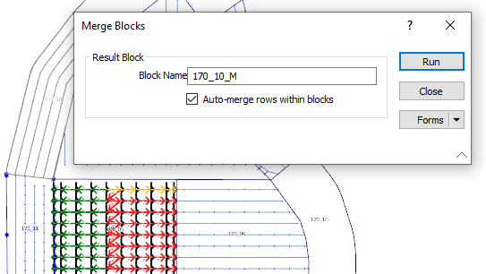
Merge Blocks. The Selection Assistant prompts for an entry block to merge and then the blocks to merge with the entry block. The option to auto merge rows within the selected blocks is available for selection:
![]()
Import from IREDES
On the Mining | Blast Design tab, in the Import/Export group, you can now select an option to import blasthole data from files in IREDES (*.xml) format.
Optionally, a default hole diameter and a block name can be specified for the imported drillhole data. If any hole is located outside of the boundary of a specified block, a warning message is displayed and the outside holes are added to a newly-created block.
If a Block name is not specified, all holes are added to a newly-created block.

Firing Sequence Animation
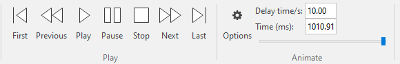
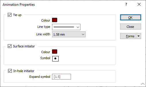
Firing sequence animation tools are now available on a new Charging ribbon. Use the Playback buttons or the Slider control to move backwards or forwards one step at a time. The animation speed can be controlled by entering a value in milliseconds per second. A negative value can also be entered to rewind the animation. Alternatively, a time (duration) for the animation can be set.
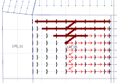
A line type and colour can be selected for the tie-in lines and the symbol selected for the surface initiators. In-hole initiators can also be animated by expanding the symbol chosen for the surface initiators.
Assign Charge Template
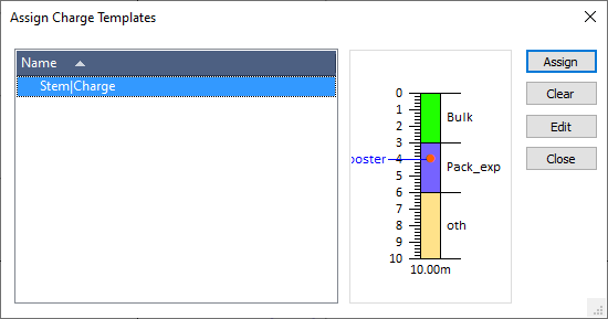
On the Charging tab, in the Charging group, when you click Assign Templates to assign a charge template to selected drillholes during mining production, a visualisation of the selected charge template is now shown:
Consumables Reporting
Packaged explosive quantity and cost calculations are now accounted for and reported as the total package length used during blasting and are not reported on a per-hole basis.