Ring Design
This
Arrange Rings on Drive
On the Mining | Ring Design tab, in the Edit group, you can now select an option to create rings with boundaries which are determined by the proximity of a selected ore body and arrange those rings along the drive using the specified burden distance between them.

Ring Wireframe Report
On the Mining | Ring Design tab, in the Report group, when you click Ring Wireframe Report to generate wireframes which represent the area that will be blasted for selected rings on a drive, you can now select an option to dynamically generate wireframe slices using Previous and Next ring boundaries:
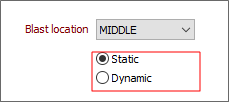
| Mode | Description |
|---|---|
| Static | Select this mode to generate planned blast wireframes with a fixed blast advance. |
| Note: This option will provide a single estimate of the blasted wireframe of a ring. Overbreak may be overestimated using this option. | |
| Dynamic | This option will generate wireframes aligned with a multi-ring blast. Using this option, estimated overbreak and underbreak are minimised. |
| This mode is the best option for curved drives. |
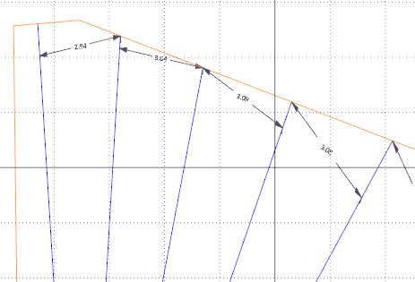
Display Drillhole Spacing
A Display Drillhole Spacing option has been added to the Mining | Ring Design ribbon. The new option will toggle the display of annotations for the distance between the holes on each ring.
![]()
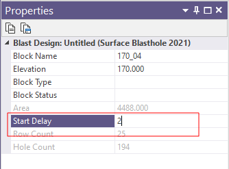
Start Delay
It is now possible to define a per-block firing sequence Start delay value other than zero via the Properties Pane when a block is selected in Vizex:
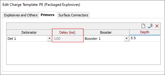
Blast Delay
Delay (ms) information has been added to the Primers tab on the Charge Templates form. The new column displays the delay in milliseconds (configured in the Consumables Library) for the selected detonator:
Surface Connectors
On the Surface Connectors tab of the Consumables Library form, to improve visualisation of the design layer, a label colour can now be assigned to surface connectors:
