Point Cloud to Solid
![]()
Input
Double-click, or click on the Select icon, to navigate to the location of the file that contains imported point cloud data. This will typically be a data file with a .DAT or .SVY file extension.
East, North, and Z fields
Specify the names of the point coordinate fields in the Input file.
Options
Maximum triangle edge length
Accept the default value or enter a maximum length for the triangle edges. Click the Auto button to restore an automatically calculated default value.
Downsample resolution
Accept [AUTO] as the default or enter a value to filter out data points that are closer to one another than the specified resolution.
Fill Holes
Select this option to enable hole filling. You should leave this check box unchecked if the surface being modelled is consistently well sampled across the point cloud. Otherwise, holes in the point cloud will be filled by large triangles and this may produce a “webbing effect”. If this is the case, use the Webbing removal slider to perform de-webbing. A positive value (typically 0.5 to 2.0) should be entered, or selected using the slider, where a higher value corresponds to more aggressive de-webbing. The default value is 0, which disables the de-webbing feature.
Simplify Wireframes
Select this option to reduce the number of vertices in the triangulation by eliminating those points that can be removed without causing the triangulation to move by more than the specified tolerance values:
- Planar Tolerance. This is the maximum amount that the triangulation is allowed to move in any direction after vertices are removed.
If no planar tolerance is specified, a default value of 0.01 will be applied automatically. Specifying a large planar tolerance will significantly alter the nature of the triangulation.
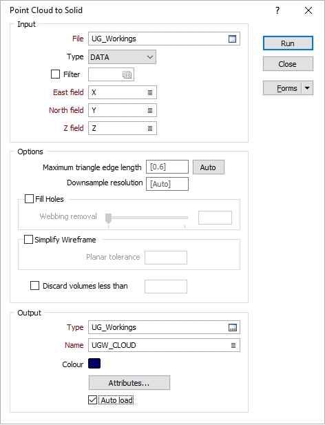
Output
Type and Name
Double-click or click on the Select icon to set the Type and Name of the wireframe that will be generated from the point cloud.
Colour
Double-click the icon to set a colour for the Output wireframe.
Attributes
Click the Attributes button to set attributes for the wireframe output.
User-defined attributes may be mapped against the fields in the Input file. It is also possible to specify a default value for each attribute. Default values are used when a corresponding value in the Input file is either missing or is not mapped.
Discard volumes less than
If this option is selected, all independent triangle shells with a volume less than the specified minimum volume will be removed.
Any value less than or equal to zero will disable volume removal.
Auto load
Select this option to load the generated output in Vizex. The default draw style for an auto-loaded wireframe is 3D Shaded.