Implicit Modelling
This
Improved iso-surface generator
An improved iso-surface generator is significantly faster for most data and generates better quality wireframe output.
The variable grid marching cube algorithm is a 'primal' marching cube rather than a 'dual' grid marching cube algorithm. In other words it works with true cubes rather than distorted 'dual' cubes.
An advantage of working with true cube is that the cubes are always convex, and hence applying the standard marching cube algorithm will always produce valid wireframes. Dual cubes on the other hand are distorted cubes which can sometimes be concave, leading to possibly invalid wireframes.
Surface Control
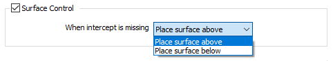
A new option has been added to the Options tab of the Contact Lithology Modelling form.
Select the Surface Control check box to choose whether the surface should be placed above drillholes, or below drillholes, when lithology codes are missing in adjacent holes.
-
Place surface above ensures the contact surface will pass over drillholes with no intercepts,
-
Place surface below ensures the surface passes under drillholes with no intercepts.
Note: If Surface Control is not enabled, then the function will decide which drillholes are passed under or passed over by the contact surface, in such a way that the curvature of the surface is minimised.
Intercepts to Model
New surface generation options have been added to the Input tab of the Contact Lithology Modelling form:
Surface type
Select a generation method that will be used to build the input surface/solid points:
| ROOF | Construct a surface that touches the top contact of each intercept. |
| MIDDLE | Make the surface pass through the middle of each intercept. |
| FLOOR | Construct a surface that touches the bottom contact of each intercept. |
Intercepts to model
Select which intercept to model where a drillhole contains more than one intercept:
| FIRST | Ignore all except the first intercept. |
| LAST | Ignore all except the last intercept. |
| ALL | Model all intercepts. The function will attempt to construct a surface that bends around to touch all intercepts. |
Input Points
The Vein Modeller can now use a "0" value from the input points to pinch out a vein.
Zero-valued extra input points are treated as pinch points, independent of the When vein code is missing option on the "Options" tab. That is, if zero-valued extra input points are specified, and "Ignore" is selected for the When vein code is missing option, then the vein will pinch as the locations indicated by the extra input points, but not where drillholes do not contain any contact intervals.
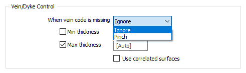
Min and Max Thickness
Optional Minimum and Maximum thickness parameterscan now be set for the vein model. The Min thickness parameter defaults to 0 (i.e. not set). The Max thickness parameter defaults to [Auto], which equals the length of the longest contact interval. Enter a value of 0 to disable the maximum thickness condition.
If Pinching is specified, then the Min thickness condition is only enforced in regions away from the pinch points. Both Min and Max thickness conditions are never enforced near contact points, since the vein thicknesses there are dictated by the contact intervals.
Surface Control
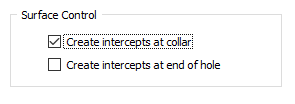
The Intrusion Modeller and the Contact Modeller now support the generation of collar and end points. Two new options have been added to the Input tab of the forms:
-
When the Create intercepts at collar check box is selected, if an INCLUDED interval begins at the collar, a contact point will be created at the collar.
-
When the Create intercepts at end of hole check box is selected, if an INCLUDED interval ends at the end of the hole, a contact point will be created at the end of the hole.