Curved Drillhole From Collar

A drillhole design in which the direction of the drillhole string is the same as the drilling direction, is a From Collar design, running from the collar to the target.
Starting from the collar is the natural way to design a drillhole when the collar location is known and the target location is to be determined. You can design straight or curved up-holes or down-holes from the collar
Micromine uses the segment length to control the length of each string segment that represents a curved hole. When the strings are converted to collar and survey files, the segment length also determines the interval between successive downhole surveys.
The safest way to plan a curved hole is to start by interactively adding segments until the hole is the right length. You can then design other holes using total length once you get a feel for how they relate to your project area.
If a compatible layer is not open. or is not the active layer, you will be prompted to create or select an active layer.
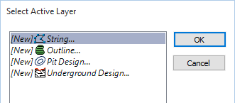
Digitise a point as the collar location and then right-click to bring up the Plan Curved Drillhole From Collar form.
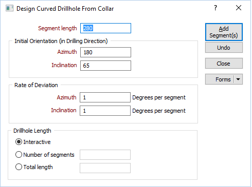
Specify the segment length and the length, orientation, and deviation of the hole.
Segment length
Enter a segment length (in grid units).
Initial Orientation (in Drilling Direction)
Enter an Azimuth and an Inclination for the initial segment of the trace. The segments you add will deviate from this start orientation.
Regardless of the design direction (from collar or from target), Micromine always expects the orientations and deviations to be specified in the drilling direction, not the design direction.
For example, if you are designing a from-target hole, which will be drilled at -60° towards the east (090°), then you should enter an inclination of -60 and an azimuth of 90, even though you are designing the hole upwards from the target. Micromine will automatically reverse the directions and deviations for you.
The drilling direction and design direction are independent variables.
Rate of Deviation
The segments that you add to the string will deviate in their orientation, over a specified segment length and by a specified Azimuth deviation and Inclination deviation, measured in degrees per segment. Deviations are defined in terms of the drilling direction.
Use the rate of deviation options with care. Drillhole deviation is the result of a complex interaction between the drilling parameters (bit type, feed pressure, rotation speed etc.), the cutting or hammering action of the bit, the rocks through which the hole passes, and the angle between the drill bit and the fabric of the country rock. Changing any one of these parameters may result in significantly different rates of deviation compared to other holes.
In a new project area you should plan for straight holes until you have enough drilling to understand how the prior holes deviated. Even with this knowledge you should always consider any planned deviation to be an approximation of the completed drillhole.
Drillhole Length
Interactive
Select this option to adjust the length of the hole interactively rather than specify a total length or calculate the length based on the number of segments.
Number of segments
Multiple segments can be added using the same orientation or the same deviation specified in the form. Enter the number of segments to create.
Total length
Enter the length of the hole (in grid units).
Add Segment(s)
Click the Add Segment(s) button to add one or more segments of the specified length and orientation.
Undo
Click Undo to undo one or more of the segments you have added.
Close
Click Close to close the form.
Forms
Click the Forms button to select and open a saved form set, or if a form set has been loaded, save the current form set.